
Biaxial solar tracker

A solar tracker, solar technology, used in solar collectors, solar collector controllers, mobile/directional solar collectors, etc.

Inactive Publication Date: 2010-02-10
SOLTEC ENERGIAS RENOVABLES
View PDF4 Cites 11 Cited by
  • Summary
  • Abstract
  • Description
  • Claims
  • Application Information

AI Technical Summary

Problems solved by technology

Said structure is made up of a series of supporting arms and transverse members to give it some rigidity, but despite its structure it also has the drawbacks of the two mentioned documents, namely that the base of the structure is rotatably connected directly to the respective On a circular track, the diameter of the circular track is substantially equal to the width of the structure and the width of the panels, including the mentioned design constraints on span

Method used


Image

  • Biaxial solar tracker
  • Biaxial solar tracker
  • Biaxial solar tracker

Examples


Embodiment Construction

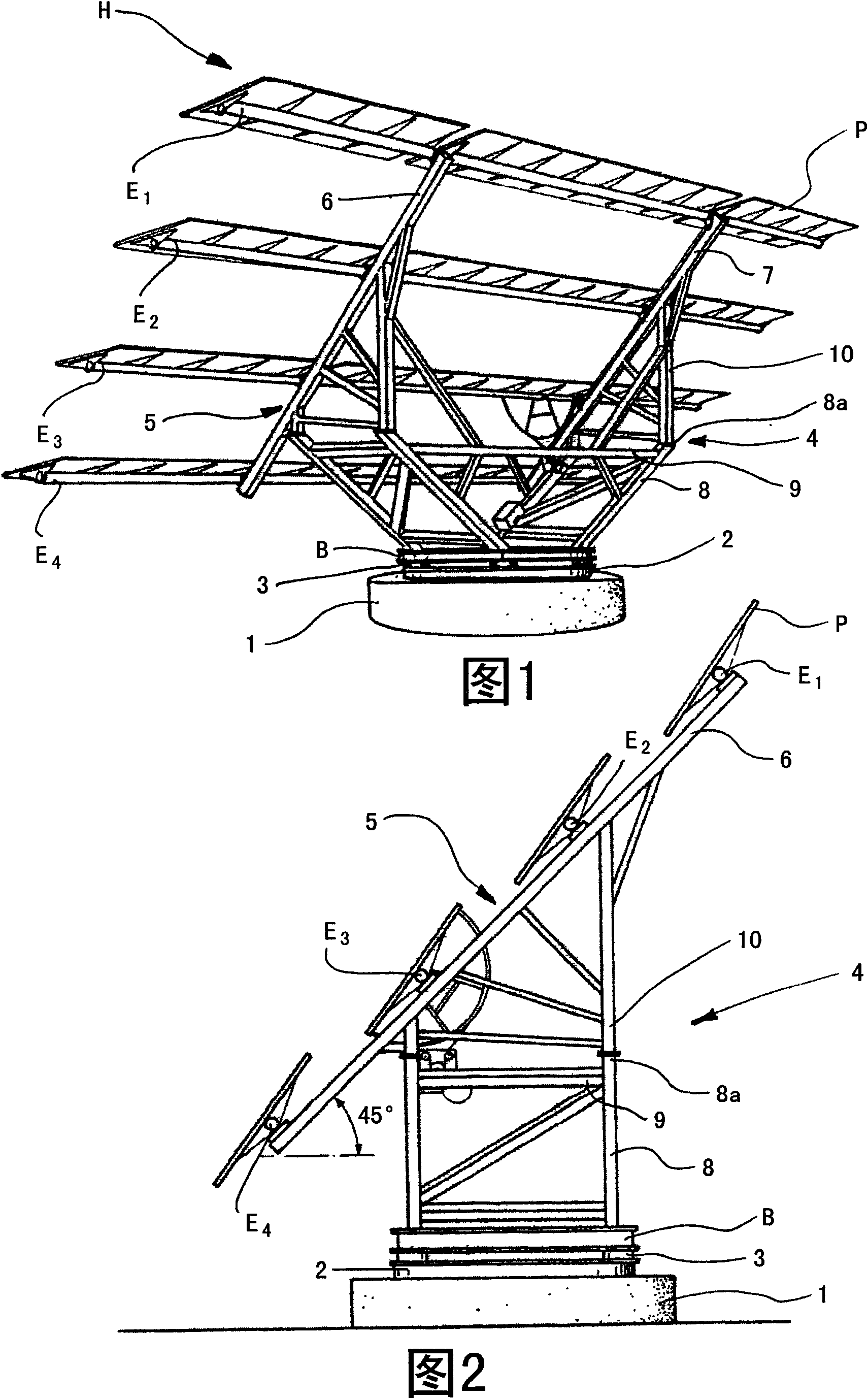
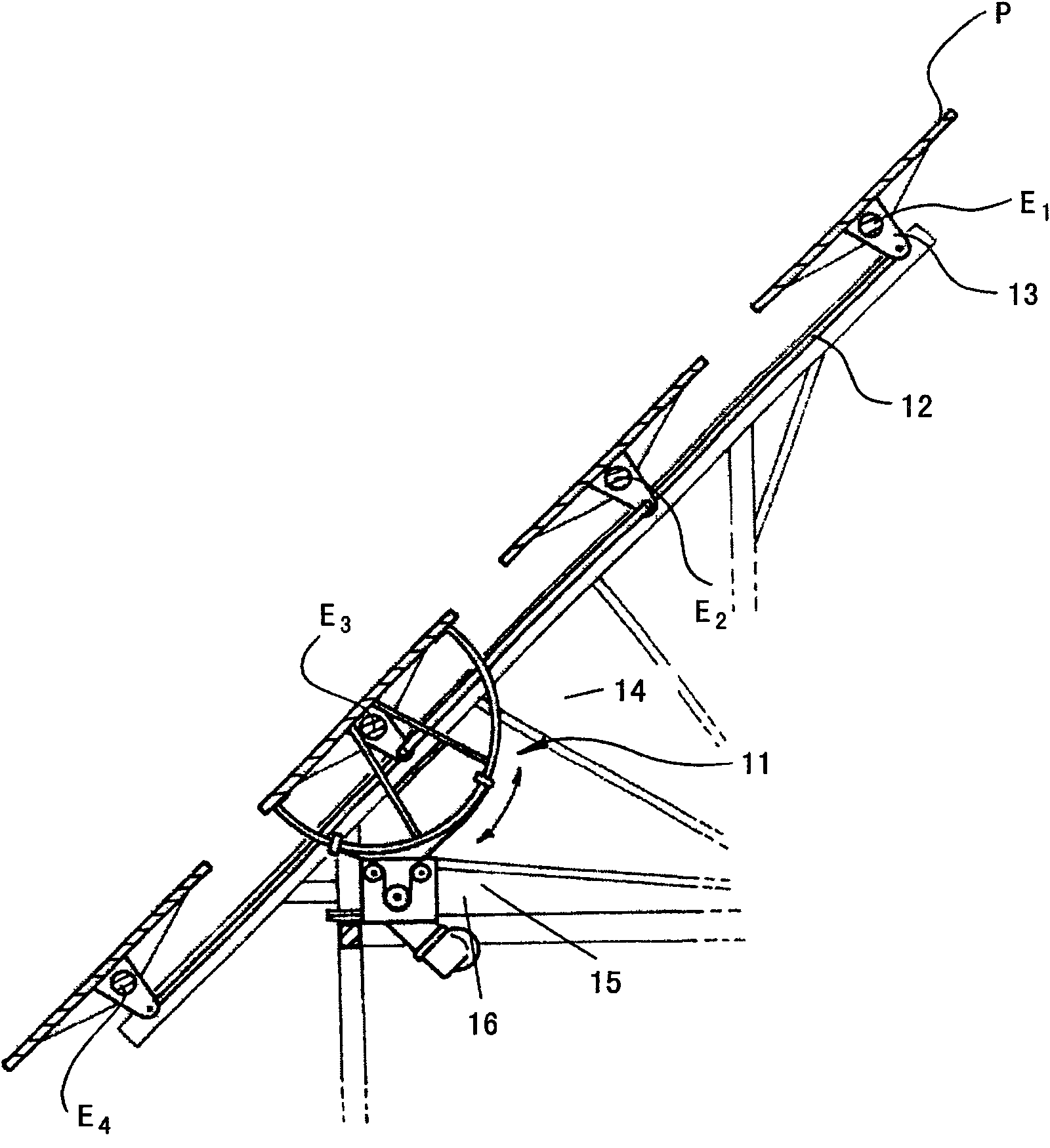
[0033] The figures illustrate two embodiments of the proposed solar tracker comprising a series of common elements, however they also have some alternative elements or structures.

[0034] Figures 1 to 3 The first embodiment is illustrated in , while Figures 5 to 8 A second embodiment is illustrated in .

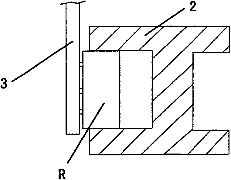
[0035] Both embodiments show the main elements forming (as previously described) the proposed solar tracker of the invention, a solar tracker of the type comprising a horizontal fixed platform 1 supporting a circular path or track 2, rolling elements R (see Figure 4 ), the rolling element is supported on said track 2, and the rolling element is connected with a movable frame 4, which includes a tilting structure 5, which has a plurality of solar panels P associated therewith, the plurality of solar cells The panels are combined into rows H, and the panels P of each row H are connected to the corresponding support shaft, which is in Figures 1 to 3 The first example show...


PUM


Abstract

The invention comprises a fixed platform (1) bearing a circular rail (2), supporting rolling elements to which is attached a mobile frame (4) with a sloping structure (5) which holds a number of solarpanels (P), grouped in rows (H), the panels (P) of each row (H) being connected to corresponding support shafts (E1-E4), supported on said sloping structure (5), and means for moving the frame (4) and shafts (E1-E4) in accordance with a predetermined configuration. The frame (4) includes a base (B) with attached thereto said rolling elements and the sloping structure (5) is raised above said base(B), at a distance from the fixed platform (1) and formed by two supporting beams (6, 7) that delimit an oblique plane and are separated from each other by a distance greater than the diameter of therail (2).

Description

technical field [0001] The present invention relates to the field of photovoltaic solar installations, aimed at using solar energy by converting it directly into electrical energy, and more particularly to controlling its motion very accurately based on synchronizing with the position of the sun at all times and incorporating or combining several photovoltaic modules Or those installations of active sun trackers of panels (ie on an orientable biaxial support structure). The support structure of the tracker allows to track the sun's trajectory from the moment it rises in the east to the moment it sets in the west through the coordinated movement of its several parts, so that the solar panels always face the sun directly. Background technique [0002] Different solutions are known in relation to sun trackers, also known as sun orientation devices, which consist of a control mechanism and allow the orientation of a series of solar panels throughout the day so that the sun is in...

Claims


Application Information

Patent Timeline
Patent Type & Authority Applications(China)
IPC IPC(8): F24J2/54F24S50/20
CPCF24J2/542H01L31/0422F24J2002/5468F24J2002/5479Y02E10/50Y02E10/47F24S30/452F24S2030/136F24S2030/145H02S20/10H02S20/32
Inventor T·格兰特R·莫拉莱斯·托里斯
Owner SOLTEC ENERGIAS RENOVABLES
Learn More