Eureka AIR delivers breakthrough ideas for toughest innovation challenges, trusted by R&D personnel around the world.

Power router and method for controlling same, computer-readable medium, and power network system

a technology of power router and control method, which is applied in the direction of wind energy generation, instruments, ac network circuit arrangements, etc., to achieve the effect of appropriate management or control of power router

Inactive Publication Date: 2016-11-17
NEC CORP
View PDF4 Cites 3 Cited by
  • Summary
  • Abstract
  • Description
  • Claims
  • Application Information

AI Technical Summary

Benefits of technology

This patent helps to manage or control power routers in a system where power cells are connected to each other asynchronously. This helps to create a more organized and efficient power network.

Problems solved by technology

For building a power supply system, it is a significant challenge to expand a power transmission network more stably and, moreover, configure a system capable of introducing a large amount of natural energy.

Method used


Image

  • Power router and method for controlling same, computer-readable medium, and power network system
  • Power router and method for controlling same, computer-readable medium, and power network system
  • Power router and method for controlling same, computer-readable medium, and power network system

Examples


exemplary embodiment 1

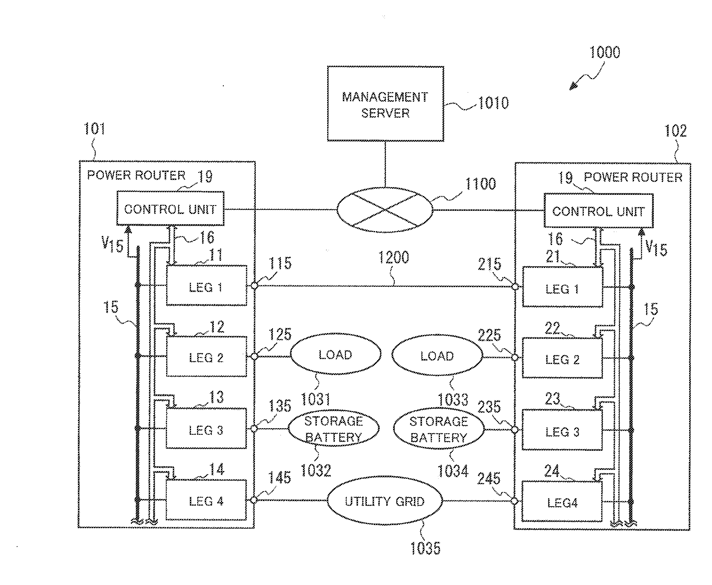
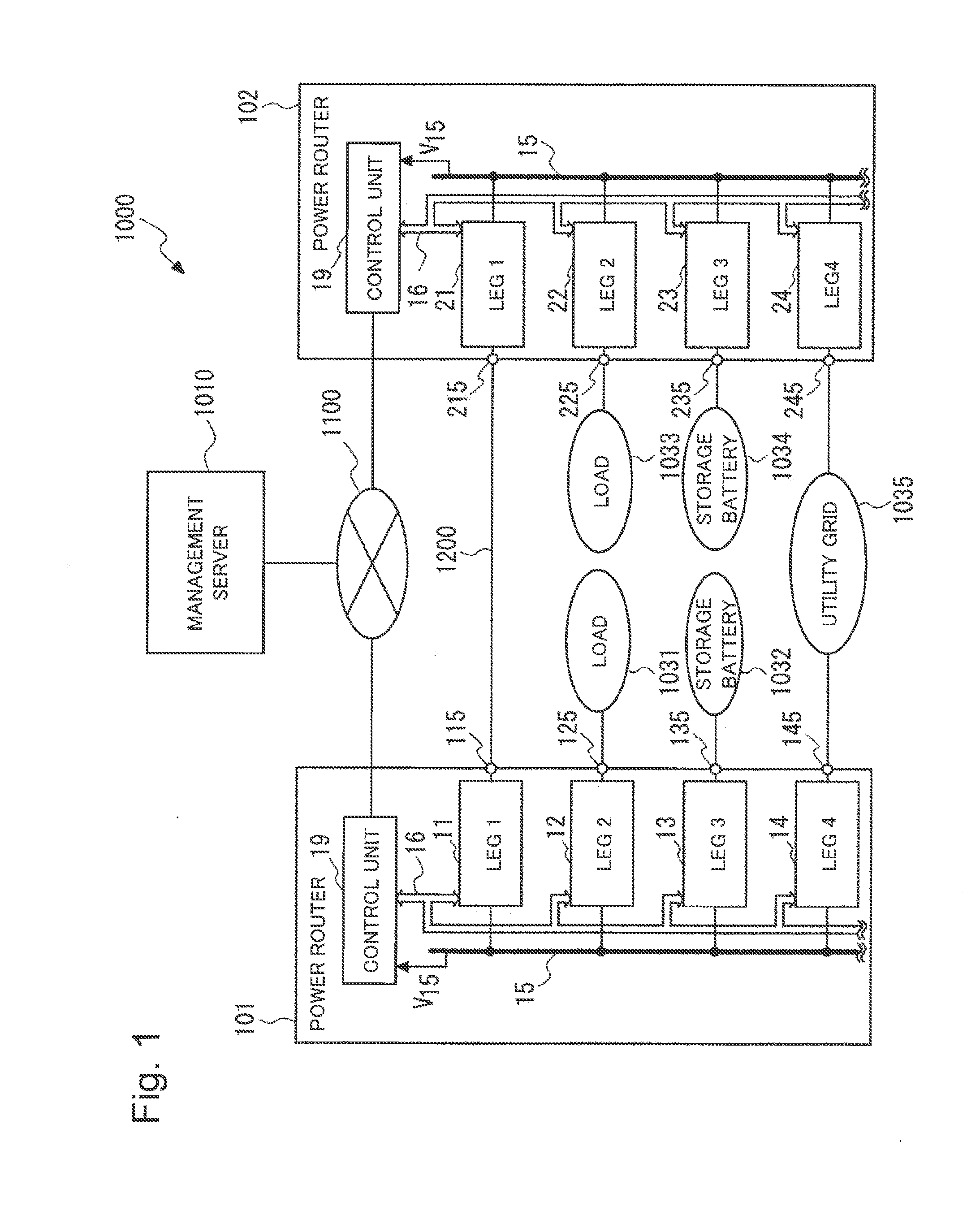
[0064]A power network system 1000 according to an exemplary embodiment 1 will be described. FIG. 1 is a block diagram illustrating a schematic configuration of the power network system 1000 according to the exemplary embodiment 1. The power network system 1000 has a management server 1010 and a plurality of power routers. In the present exemplary embodiment, an example in which the power network system 1000 having the management server 1010, power routers 101 and 102, and a transmission line 1200 will be described. The power routers 101 and 102 are specific examples of the above-described power routers 841 to 844 (see FIG. 23). Hereinafter, the management server is also called a management means.

[0065]The power network system 1000 and a power network system to be described in the following exemplary embodiment have a configuration for correcting power transmission loss between power routers by power control. In general, when power is transmitted via a transmission line, transmission...

case 1

[0207]The case where power received in the first stand-alone leg 63 is 2 [kW] (W1=2 [kW]) and power received in the second stand-alone leg 64 is 1 [kW] (W2=1 [kW]) will be described. FIG. 15 is a diagram illustrating the power router 600 when power received in the first stand-alone leg 63 is 2 kW (W1=2 kW) and power received in the second stand-alone leg 64 is 1 kW (W2=1 kW). In this case, the power router 600 receives power of 3 [kW] from the outside. Thus, the power router 600 has to be able to transmit power of 3 [kW] at maximum via the master legs. In this case, the control unit 19 calculates the coefficient u from Equation 3 above as expressed by the following Equation 6.

Equation6u=2+13+2=0.6(6)

[0208]In this case, the coefficient u is 0.6. Thus, by Equation 4 above, the transmission power of the first master leg 61 is 1.8 [kW] (=0.6×3 [kW]). By Equation 5 above, the transmission power of the second master leg 62 is 1.2 [kW] (=0.6×2 [kW]).

case 2

[0209]The case where power received in the first stand-alone leg 63 is 1 [kW] (W1=1 [kW]) and power received in the second stand-alone leg 64 is 1 [kW] (W2=1 [kW]) will be described. FIG. 16 is a diagram illustrating the power router 600 when power received in the first stand-alone leg 63 is 1 kW (W1=1 kW) and power received in the second stand-alone leg 64 is 1 kW (W2=1 kW). In this case, the power router 600 receives power of 2 [kW] from the outside. Thus, the power router 600 has to be able to transmit power of 2 [kW] at maximum via the master leg. In this case, the control unit 19 calculates the coefficient u from Equation 3 above as expressed by the following Equation 7.

Equation7u=1+13+2=0.4(7)

[0210]In this case, the coefficient u is 0.6. Thus, by Equation 4 above, the transmission power of the first master leg 61 is 1.2 [kW] (=0.4×3 [kW]). By Equation 5 above, the transmission power of the second master leg 62 is 0.8 [kW] (=0.4×2 [kW]).

[0211]When, for example, the setting of t...


PUM


Abstract

The purpose of the present invention is to enable a power router to be more suitably managed or controlled when constructing a power network system in which power cells are asynchronously interconnected. A power router has a first master leg, a second master leg, a first stand-alone leg, and a second stand-alone leg. Based on the power transmitted and received by the first stand-alone leg and the second stand-alone leg, a control unit controls the power transmitted and received by the first master leg and the power transmitted and received by the second master leg.

Description

TECHNICAL FIELD[0001]The present invention relates to a power router and a control method thereof, a computer readable medium, and a power network system.BACKGROUND ART[0002]For building a power supply system, it is a significant challenge to expand a power transmission network more stably and, moreover, configure a system capable of introducing a large amount of natural energy.[0003]As a novel power network, a power network system called a digital grid (registered trademark) has been proposed (PTL 1 and PTL 2).[0004]The digital grid (registered trademark) is a power network system in which a power network is divided into small-scale cells and the cells are asynchronously connected to one another. Each power cell which is small has a scale including one house, building, or commercial facility. Each power cell which is large has a scale including a prefecture, a city, a town, and a village. Each power cell includes a load and, in some cases, a power-generating facility and a power st...

Claims


Application Information

Patent Timeline
Patent Type & Authority Applications(United States)
IPC IPC(8): G05F1/66H02J3/38
CPCG05F1/66H02J3/386H02J3/383H02J3/382Y04S40/124H02J13/00017H02J13/00016Y02E10/56Y02E10/76Y02E60/00
Inventor KOBAYASHI, NORIAKI
Owner NEC CORP
Why Eureka
Eureka Blog
Learn More