Lever-type connector

Active Publication Date: 2016-11-17
SUMITOMO WIRING SYST LTD
View PDF8 Cites 7 Cited by
  • Summary
  • Abstract
  • Description
  • Claims
  • Application Information

AI Technical Summary

Benefits of technology

[0011]The lever may have a flat plate-shaped arm and a substantially U-shaped slit may penetrate in a plate thickness direction of the arm. An area surrounded by the slit may define the resilient arm. An inner surface of the sli

Problems solved by technology

The follower pin is inserted into the cam groove when the two housings are fit lightly, and a lock re

Method used


Image

  • Lever-type connector
  • Lever-type connector
  • Lever-type connector

Examples


Example

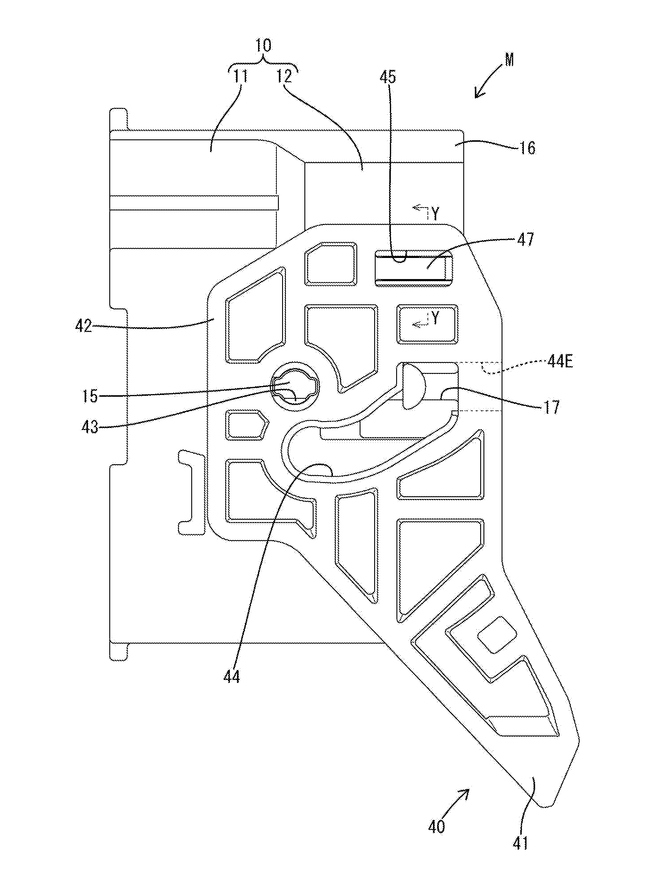
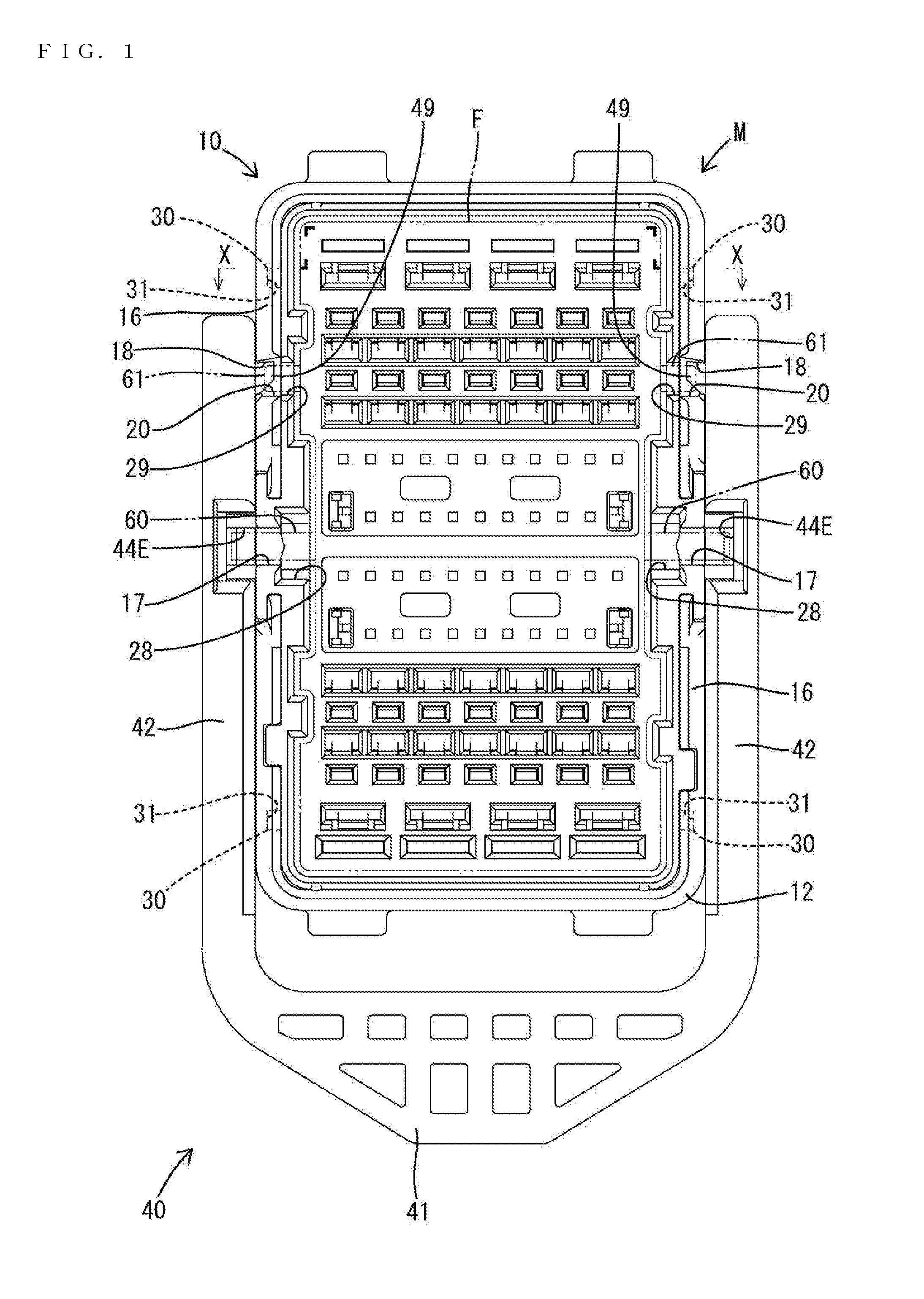
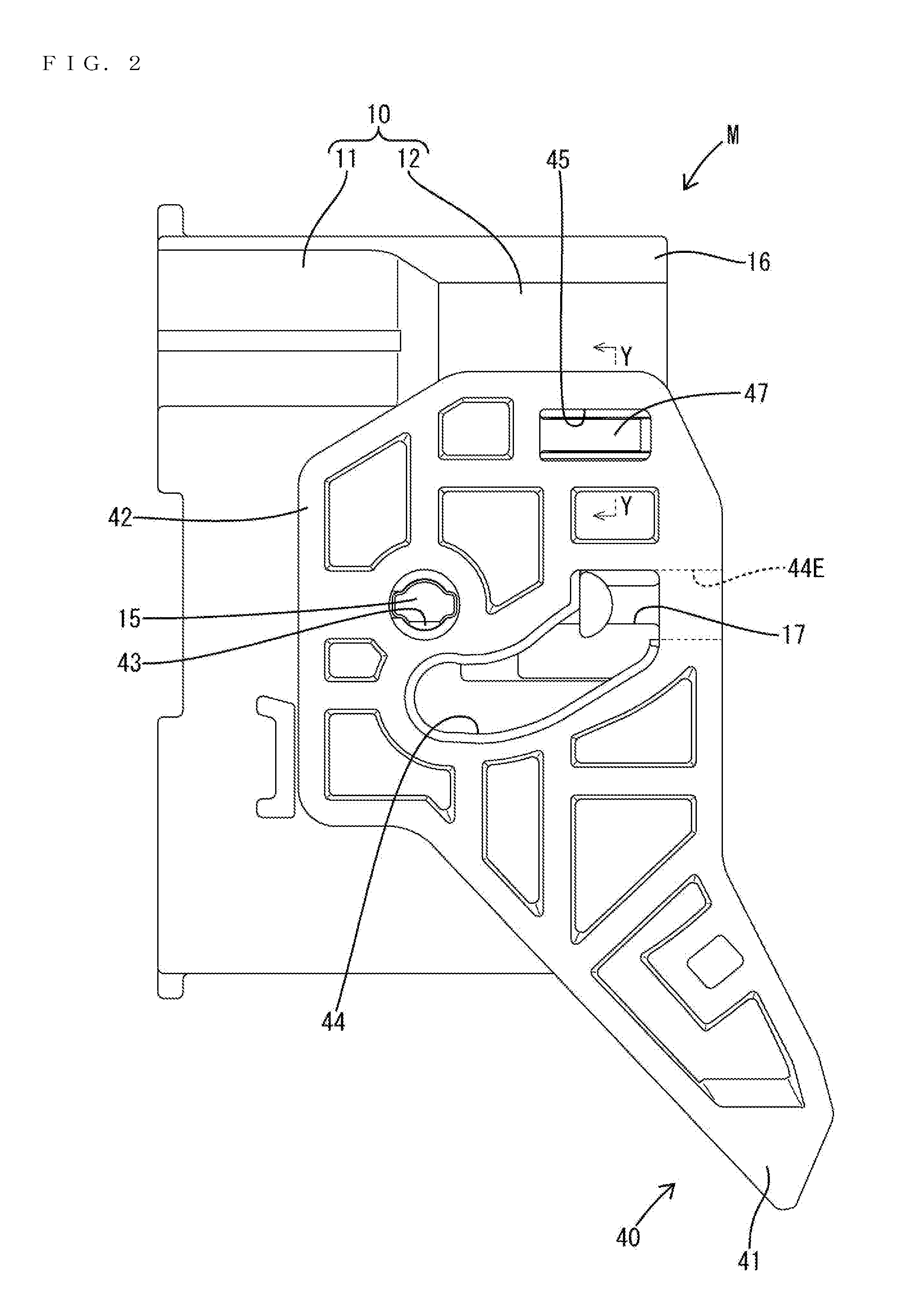
[0020]An embodiment is described with reference to FIGS. 1 to 8. Note that, in the description of a lever-type connector M, a right side in FIG. 2 and a lower side in FIGS. 7 and 8 are defined as a front concerning a front-back direction for convenience sake. Left and right directions in FIG. 1 are defined as left and right directions concerning a lateral direction. Up and down directions in FIGS. 1 to 6 are defined as up and down directions concerning a vertical direction.

[0021]The lever-type connector M includes a housing 10 made of synthetic resin, a moving plate 24 made of synthetic resin and a lever 40 made of synthetic resin. As shown in FIGS. 2, 7 and 8, the housing 10 is an integral assembly of a block-like terminal holding portion 11 and a rectangular tubular receptacle 12 extending forward from the outer peripheral edge of the front end of the terminal holding portion 11. As shown in FIGS. 7 and 8, male terminal fittings 13 are mounted in the terminal holding portion 11. A...


PUM


Abstract

A lever (40) is formed with resilient arms (48) cantilevered in a direction substantially perpendicular to rotary shafts (15) of the lever (40) and intersecting with a circumferential direction about the rotary shafts (15), and locking projections (49) projecting from extending end parts of the resilient arm pieces (48) and configured to hold the lever (40) at an initial position by entering locking holes (20) and being locked. The locking hole (20) is formed with a locking edge part (21) located on a surface of a housing (10) facing the lever (40) and configured to lock the locking projection (49) and a recess (23) formed by recessing an inner surface part on a deeper side than the locking edge part (21), and the locking projection (49) is formed with a hooking portion (53) configured to enter the recess (23) while being locked to the locking edge part (21).

Description

BACKGROUND[0001]1. Field of the Invention[0002]The invention relates to a lever-type connector.[0003]2. Description of the Related Art[0004]Japanese Unexamined Patent Publication No. 2013-020904 discloses a lever-type connector in which a lever is mounted rotatably on a male housing and is formed with a cam groove. A follower pin is formed on a female housing and can engage the cam groove of the lever. The two housings are connected by rotating the lever from an initial position to a connection position while the follower pin is engaged with the cam groove. A resilient locking piece is formed on the lever and has a lock that engages a locking hole on the male housing for holding the lever at the initial position. The follower pin is inserted into the cam groove when the two housings are fit lightly, and a lock releasing portion of the female housing interferes with the lock to deflect the resilient locking piece. The lock disengages from the locking hole as the resilient locking pie...

Claims


Application Information

Patent Timeline
IPC IPC(8): H01R13/629H01R13/627
CPCH01R13/6272H01R13/62938H01R13/62955
Inventor OBATA, MASAYUKI
Owner SUMITOMO WIRING SYST LTD
Why Eureka
Try Eureka