Fluid transport apparatus, method for controlling the same, and chemical synthesis apparatus

Active Publication Date: 2016-11-24
SEIKO EPSON CORP
View PDF0 Cites 1 Cited by
  • Summary
  • Abstract
  • Description
  • Claims
  • Application Information

AI Technical Summary

Benefits of technology

The invention can make a fluid flow smoother and more accurate, by reducing the pulsations in it.

Problems solved by technology

However, as described above, in the configuration of JP-A-2011-122858, since the piezoelectric elements are respectively driven in sequence so as to transfer the fluid in sequence of three circular areas, in the same manner as a case where a plurality of pumps are disposed side by side and are driven in sequence, it is not possible to suppress even the pulsation of the fluid due to displacement in an amplitude direction (thickness direction) of each piezoelectric element.

Method used


Image

  • Fluid transport apparatus, method for controlling the same, and chemical synthesis apparatus
  • Fluid transport apparatus, method for controlling the same, and chemical synthesis apparatus
  • Fluid transport apparatus, method for controlling the same, and chemical synthesis apparatus

Examples


Embodiment Construction

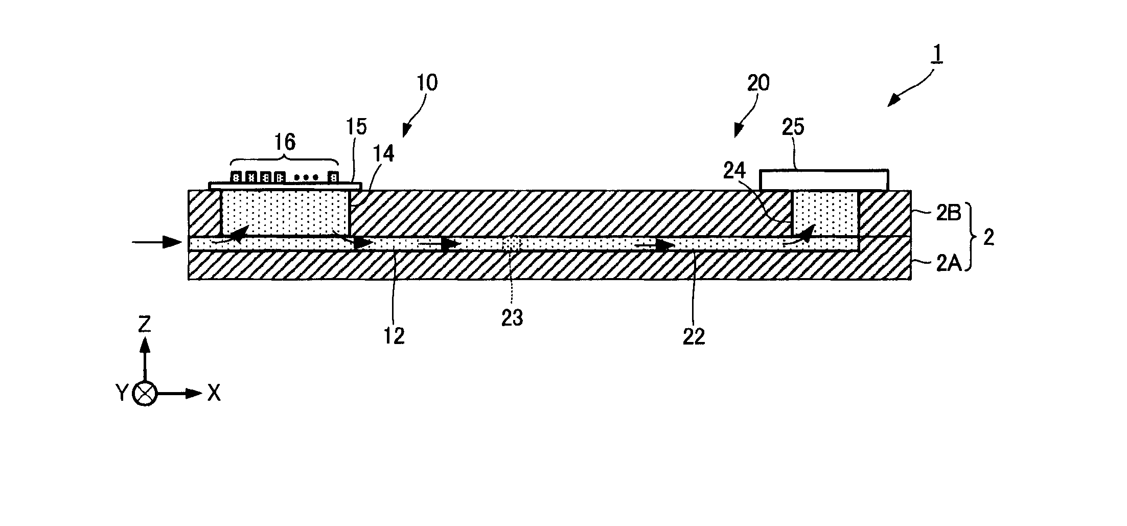
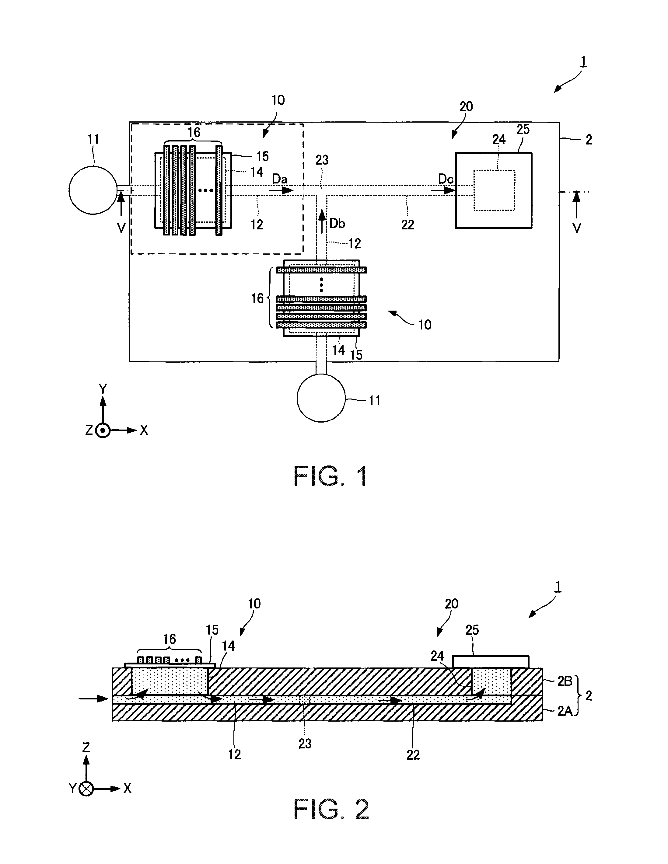
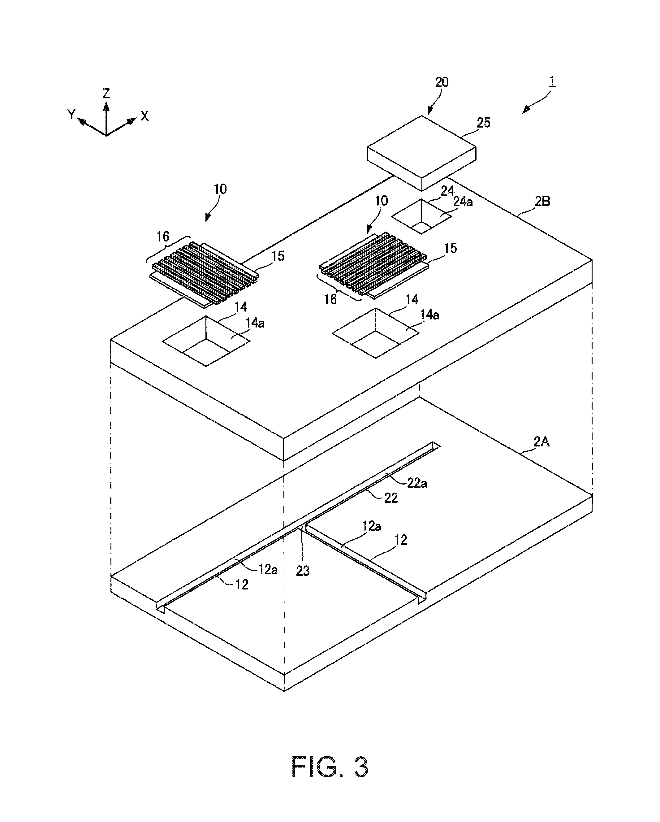
[0032]Hereinafter, a chemical synthesis apparatus according to an embodiment of the invention will be described with reference to the drawings. The scope of the invention is not limited to the following embodiments, and may be optionally changed within the scope of technical ideas of the invention. In the following drawings, a scale or a number of each structure may be different from that of an actual structure, in order to easily recognize each configuration.

Chemical Synthesis Apparatus

[0033]First, the chemical synthesis apparatus according to the embodiment of the invention will be described. The chemical synthesis apparatus described herein is an apparatus that obtains a product substance (fluid) Dc which is generated by performing a chemical synthesis with a mixture of two types of fluids Da and Db such as reagents. The fluid may be a liquid or a gas, but here, a case where two types of liquids are mixed with each other, and a product substance of the liquids is obtained is used...


PUM


Abstract

A fluid transport apparatus includes a pressure chamber to which a fluid is supplied, N drive elements that deliver the fluid to a channel by changing pressure of the fluid within the pressure chamber, and a control section that supplies a drive signal to each of the drive elements. The control section controls the N (N≧2) drive elements such that phases of drive signals which are supplied to each of the drive elements are different from each other. Therefore, by changing the pressure of the fluid within the pressure chamber while suppressing an amplitude of the drive elements as a whole, pulsation of the fluid is effectively suppressed.

Description

[0001]This application claims priority to Japanese Patent Application No. 2015-101621 filed on May 19, 2015 which is hereby expressly incorporated by reference in its entirety.BACKGROUND[0002]1. Technical Field[0003]Several aspects of the present invention relate to a fluid transport apparatus, a method for controlling the same, and a chemical synthesis apparatus.[0004]2. Related Art[0005]In the related art, for example, a micro-reactor has been used as an apparatus that performs a chemical reaction by mixing a plurality of fluids such as samples or reagents in a space of which one side is several centimeters or less. As a simple micro-reactor, there is a case where a channel is formed by carving a very small groove into a T shape on a plate. The channel includes two inflow paths into which two reagents are respectively introduced, and one outflow path, in which the reagents that are respectively introduced into the two inflow paths join with each other, and are guided to the outflo...

Claims


Application Information

Patent Timeline
IPC IPC(8): B01J14/00F15D1/02
CPCF15D1/02B01J14/00B01J19/0093B01J2219/00783B01J2219/00813B01J2219/00817B01J2219/00891B01J2219/00963B01J2219/009
Inventor SERA, HIROSHI
Owner SEIKO EPSON CORP
Why Eureka
Try Eureka