Power supply circuit breaking device

Active Publication Date: 2019-12-12
YAZAKI CORP
View PDF4 Cites 0 Cited by
  • Summary
  • Abstract
  • Description
  • Claims
  • Application Information

AI Technical Summary

Benefits of technology

The present invention provides a power supply circuit breaking device that can prevent the generation of sparks and arcs during operation. Furthermore, the device is designed to be smaller in size.

Problems solved by technology

For this reason, the lever becomes long in the power supply circuit breaking device, resulting in an increase in the size of the entire device.

Method used


Image

  • Power supply circuit breaking device
  • Power supply circuit breaking device
  • Power supply circuit breaking device

Examples


Embodiment Construction

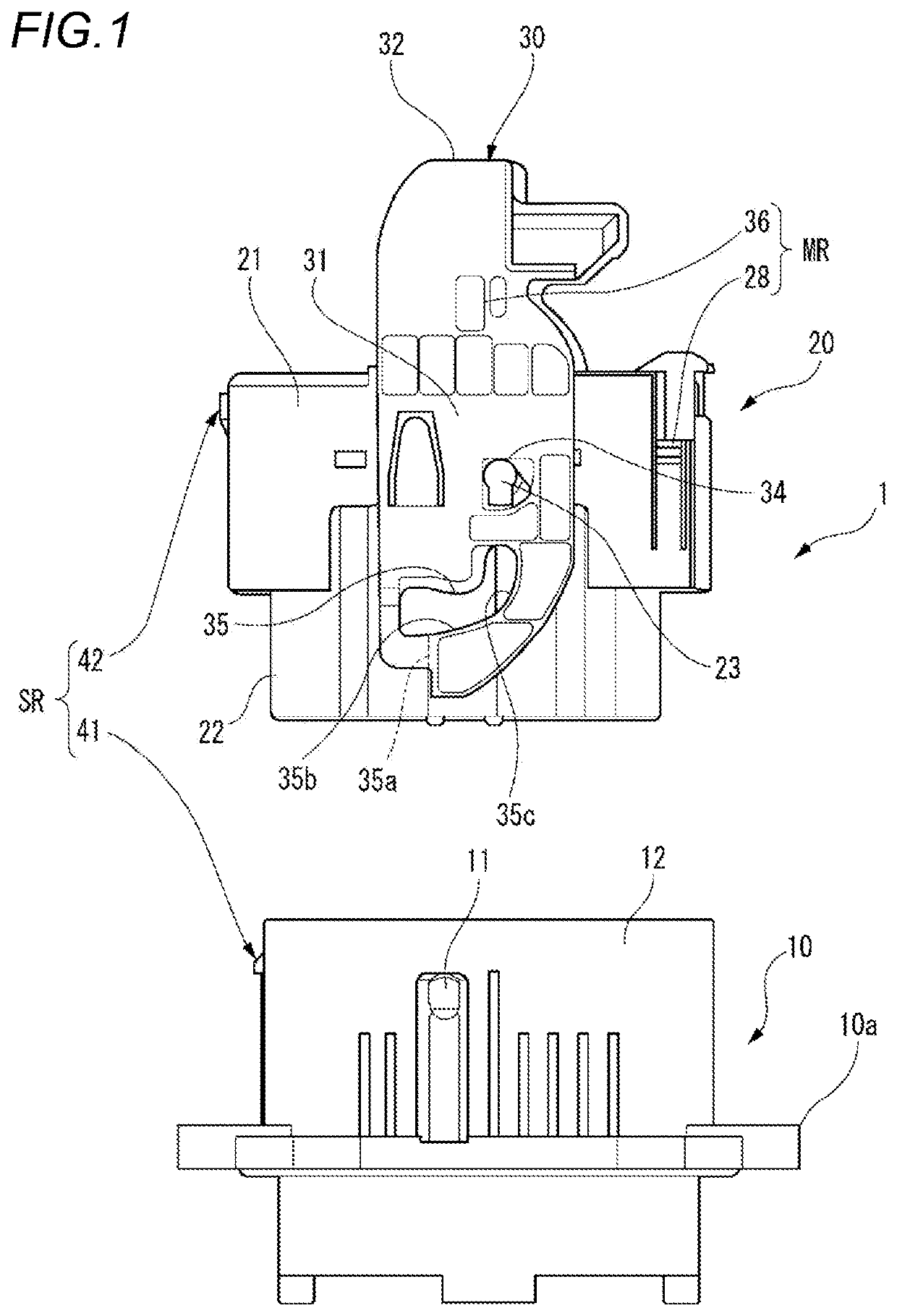
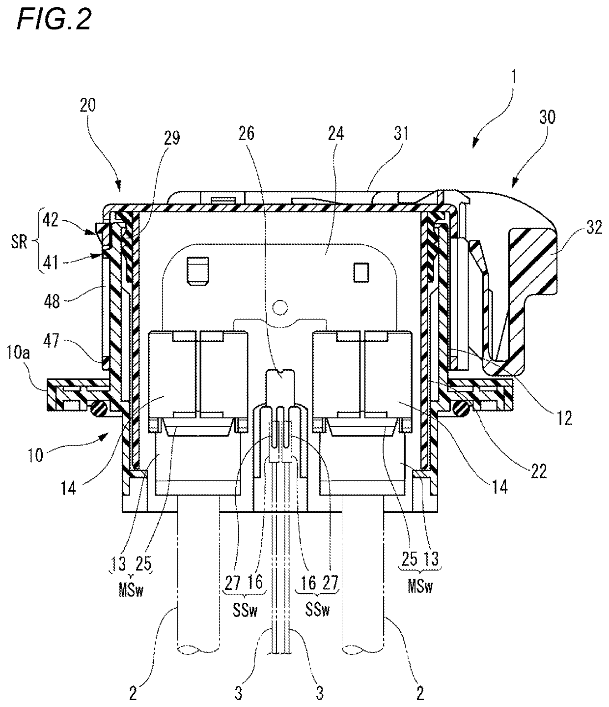
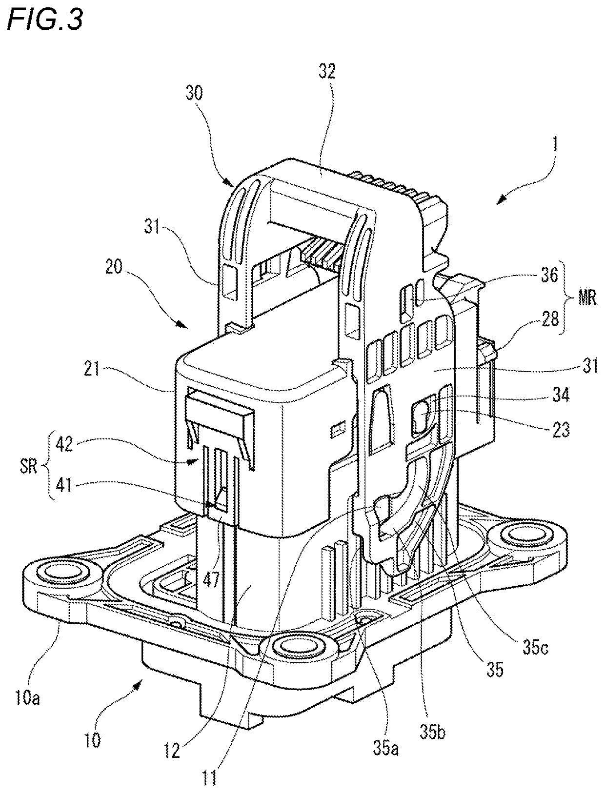
[0052]Hereinafter, an embodiment according to the present invention will be described with reference to the drawings.

[0053]FIG. 1 is a side view of a first connector housing and a second connector housing of a power supply circuit breaking device according to the present embodiment. FIG. 2 is a cross-sectional view taken along an upper-lower direction of the power supply circuit breaking device. FIG. 3 is a perspective view of the power supply circuit breaking device in which the first connector housing and the second connector housing are in a temporarily fitted state. FIG. 4 is a side view of the power supply circuit breaking device in which the first connector housing and the second connector housing are in the temporarily fitted state. FIG. 5 is a perspective view of the power supply circuit breaking device in which the first connector housing and the second connector housing are in a finally fitted state. FIG. 6 is a side view of the power supply circuit breaking device in whic...


PUM


Abstract

A power supply circuit breaking device includes a first connector housing, a second connector housing, a main lock unit locking in a finally fitted state in which the second connector housing is completely fitted to the first connector housing, a sub-lock unit locking in a temporarily fitted state in which a part of the second connector housing is fitted to the first connector housing, a main switch unit switched on in the finally fitted state and the temporarily fitted state, and a sub-switch unit switched on in the finally fitted state and switched off in the temporarily fitted state. The sub-lock unit includes a sub-lock claw formed in the first connecter housing, and an operation portion provided in the second connector housing and having an engaging plate portion engaged with the sub-lock claw in the temporarily fitted state.

Description

CROSS-REFERENCE TO RELATED APPLICATIONS[0001]This application is based on and claims priority under 35 USC 119 from Japanese Patent Application No. 2018-112041 filed on Jun. 12, 2018, the contents of which are incorporated herein by reference.TECHNICAL FIELD[0002]The present invention relates to a power supply circuit breaking device.BACKGROUND ART[0003]For example, a vehicle such as an electric vehicle or a hybrid vehicle is provided with a power supply circuit breaking device called a service plug configured to disconnect electrification between a power supply unit and a load for the purpose of ensuring operation safety in maintenance of an electrical system thereof. In such a power supply circuit breaking device, there is a unit configured to provide a time lag between on and off of a power supply circuit switch and a signal circuit switch and prevent the occurrence of sparks, arcs or the like resulting from an amount of remaining electricity after the signal circuit switch is sw...

Claims


Application Information

Patent Timeline
IPC IPC(8): H01R13/629H01H9/08H01H9/10H01R13/639H01R13/436
CPCH01R13/4362H01H9/085H01R13/639H01R13/62905H01R13/62955H01H9/104H01R13/629H01R13/70H01R13/62938H01R13/71H01R13/46H01R35/04H01R13/6295H01R13/641H01R13/701
Inventor MOTOSHIGE, YUICHI
Owner YAZAKI CORP
Why Eureka
Try Eureka