Light emitting device and light emitting device assembly

Inactive Publication Date: 2008-10-30
NEC LIGHTING
View PDF4 Cites 0 Cited by
  • Summary
  • Abstract
  • Description
  • Claims
  • Application Information

AI Technical Summary

Benefits of technology

[0007]The present invention is made in view of the above-mentioned situation, and an object of the present invention is to provide a light emitting device and a light emitting device assembly which can achieve miniaturization of a substrate and a reflecting plate.
[0010]The shape of the opening portion is such that the opening portion space on the side of the third surface of the reflecting plate is smaller than the opening portion space on the side of the fourth surface of the reflecting plate. Therefore, when the substrate and reflecting plate are in a state in which they are fixed to each other by a screw member, the screw member and the opening portion of the reflecting plate are closely arranged without the screw member and the opening portion of the reflecting plate being in contact with each other. Accordingly, since a hole for a screw member can be provided near the opening of the reflecting plate, miniaturization of the reflecting plate can be achieved, and miniaturization of the substrate can be also achieved accompanied with the miniaturization of the reflecting plate.

Problems solved by technology

After all, there is a problem that the entire light emitting device 111 is enlarged.

Method used


Image

  • Light emitting device and light emitting device assembly
  • Light emitting device and light emitting device assembly
  • Light emitting device and light emitting device assembly

Examples


first exemplary embodiment

[0021]FIG. 4 is a perspective view showing a light emitting device according to a first exemplary embodiment of the present invention. A Y direction shown in FIG. 4 is a direction in which reflecting plate 4 is placed on substrate 3 with third surface 9 of reflecting plate 4 coming into contact with first surface 7 of substrate 3. An X direction is a direction which is orthogonal to the Y direction, and in which an applied part of substrate 3 extends.

[0022]Light emitting device 1 includes at least one light emitting element 2, substrate 3, reflecting plate 4, and at least one screw member 5. Light emitting element 2 is mounted in substrate 3. Reflecting plate 4 is arranged on substrate 3. Screw member 5 fixes reflecting plate 4 and substrate 3 to each other.

[0023]Light emitting element 2 is connected to an anode and a cathode which are not shown. Also, light emitting elements 2 may be electrically connected to each other. Further, it is desirable that light emitting element 2 is a l...

second exemplary embodiment

[0030]A light emitting device assembly can be made by combining a plurality of light emitting devices described above. This light emitting device assembly can be used for an image reading apparatus such as an image scanner or a copier. Before explaining an exemplary embodiment of the light emitting device assembly, a conventional light emitting device assembly will be explained first.

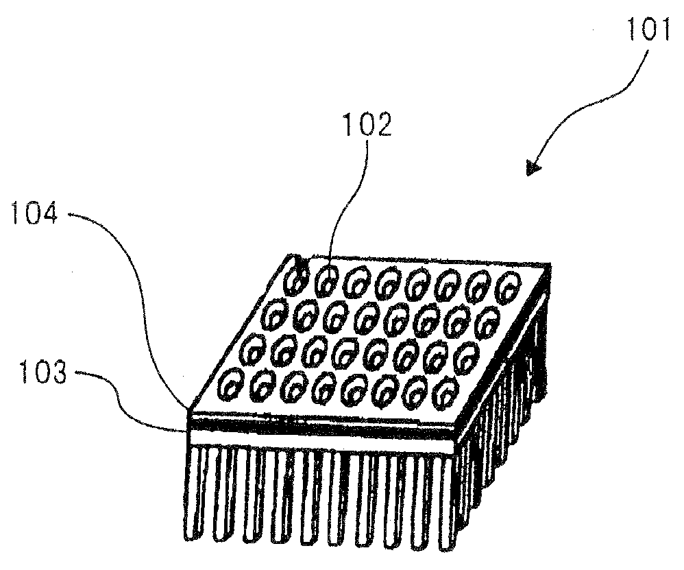
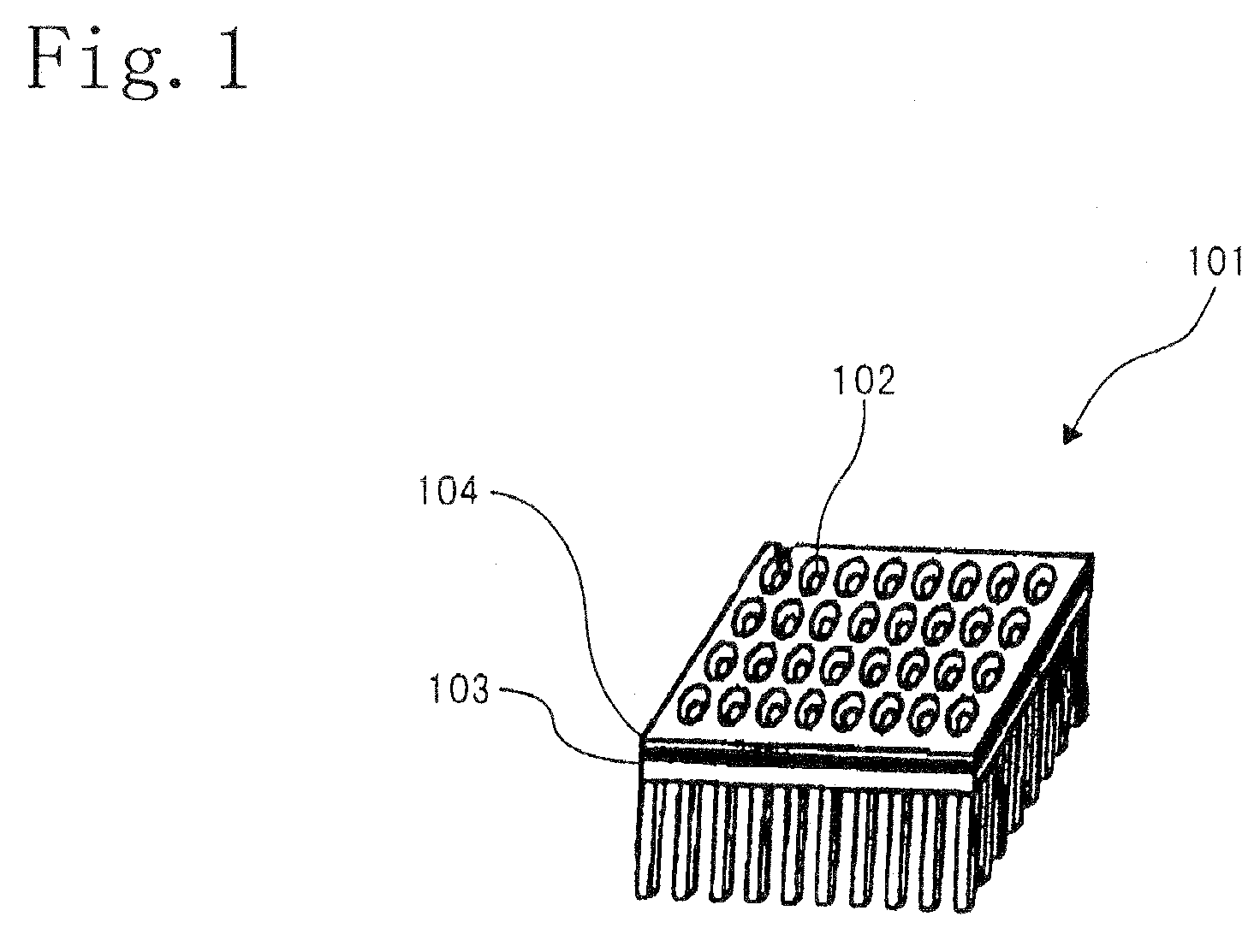
[0031]As shown in FIG. 3A, conventional light emitting device assembly 121 includes a plurality of light emitting devices 101a, 101b. Light emitting devices 101a, 101b are arranged in a line so that light emitting elements 102a, 102b, 102c, 102d are located in a line. Moreover, light emitting devices 101a, 101b are formed by a method of fixing reflecting plates 104a, 104b and substrates 103a, 103b to each other with screws 105a, 105b towards substrates 103a, 103b from fourth surface 110a, 110b of reflecting plates 104a, 104b. In this exemplary embodiment, it is necessary to provide holes for screw membe...


PUM


Abstract

A light emitting device (1) includes a light emitting element (2), a substrate (3), a reflecting plate (4), and a screw member (5). The light emitting element is mounted in the substrate. The reflecting plate is arranged on the substrate. The screw member fixes the reflecting plate and the substrate to each other. The substrate includes a first surface (7), a second surface (8) on an opposite side of the first surface, and an applied part (11) on which the light emitting element is mounted. The reflecting plate includes a third surface (9) that comes into contact with the first surface, a fourth surface (10) on an opposite side of the third surface, and an opening portion (6). The opening portion penetrates the reflecting plate and opens on the third surface and the fourth surface. The opening portion has the shape such that an opening space on a side of the third surface of the reflecting plate is smaller than an opening space on a side of the fourth surface of the reflecting plate. The screw member penetrates the first surface of the substrate and the third surface of the reflecting plate from the second surface of the substrate towards an area in which the opening portion of the reflecting plate is not formed and to which the opening portion is near, whereby the screw member fixes the substrate and the reflecting plate to each other.

Description

BACKGROUND OF THE INVENTION[0001]1. Field of the Invention[0002]The present invention relates to a light emitting device and a light emitting device assembly, and in particular, to a light emitting device and a light emitting device assembly which are used for backlights for a liquid crystal display apparatus or used for light sources for an image reading apparatus such as an image scanner or a copier.[0003]2. Description of the Related Art[0004]As shown in FIG. 1, light emitting device 101 that includes light emitting diode 102 for an illumination light source is disclosed (refer to JP-A-2003-45206). Light emitting device 101 is constituted by mounting light emitting element 102 in substrate 103 and placing reflecting plate 104 on substrate 103. As a method of fixing substrate 103 and reflecting plate 104 to each other, a method of fixing by coating of an adhesive between a surface of substrate 103 and a surface of reflecting plate 104, or by “bonding” such as sticking a double sid...

Claims


Application Information

Patent Timeline
IPC IPC(8): F21V7/04F21V7/00F21V19/00H01L33/60
CPCH01L33/60H04N1/02815H04N1/02865H04N2201/02456H04N2201/02468H04N2201/02485
Inventor OKIMURA, KATSUYUKI
Owner NEC LIGHTING
Why Eureka
Try Eureka