Gun barrel

Inactive Publication Date: 2016-11-24
XU YOU RUI
View PDF3 Cites 5 Cited by
  • Summary
  • Abstract
  • Description
  • Claims
  • Application Information

AI Technical Summary

Benefits of technology

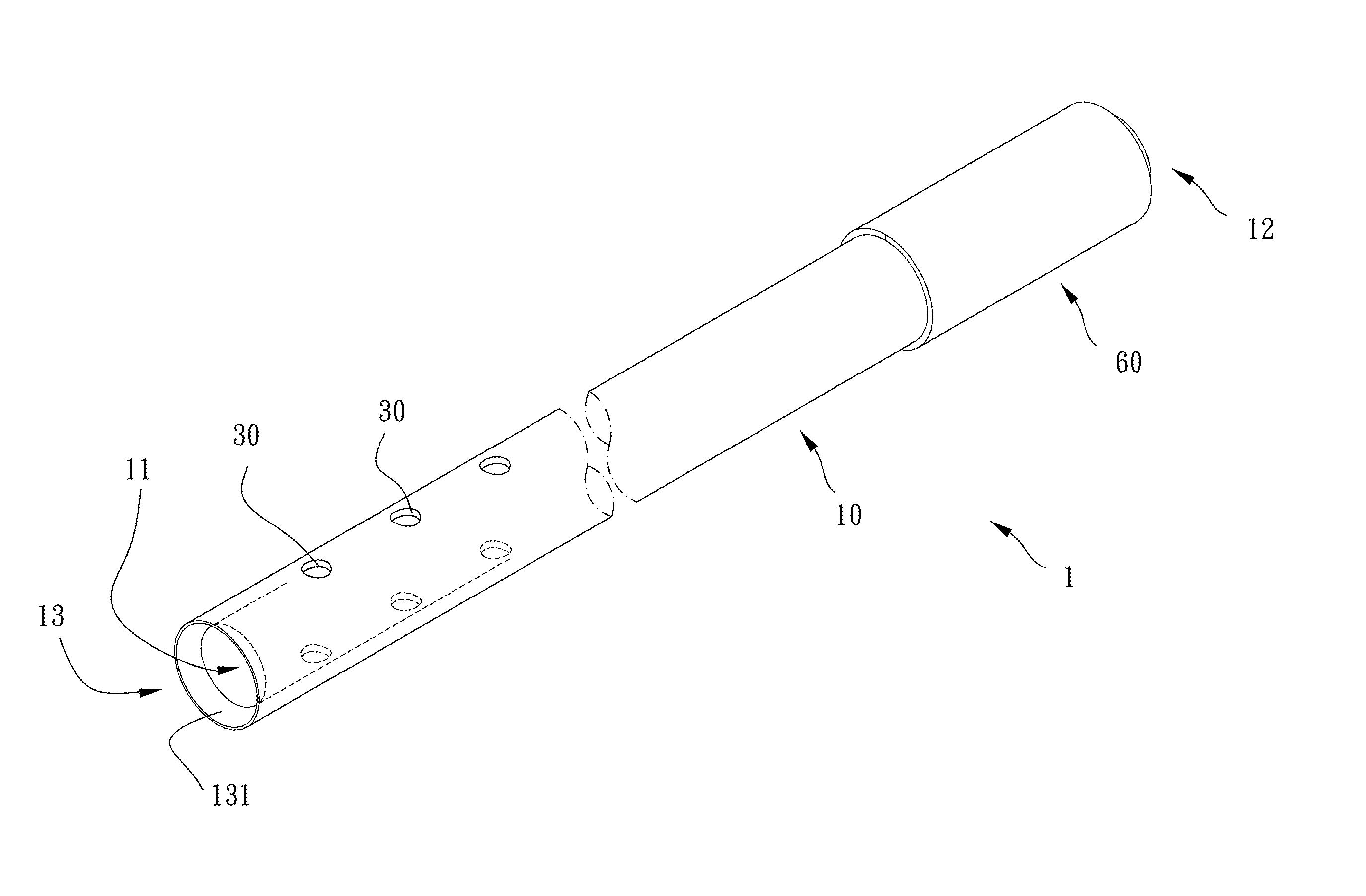
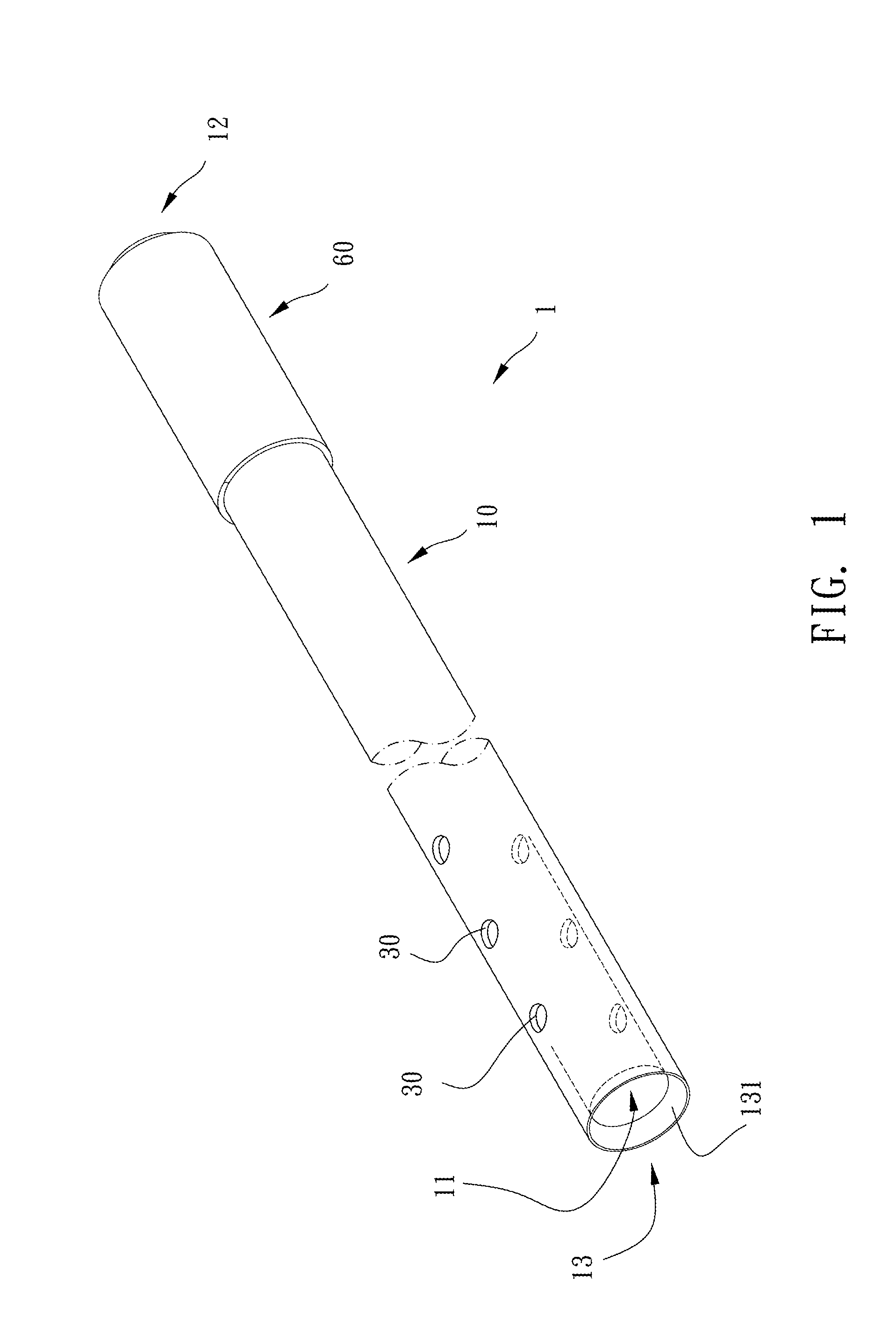
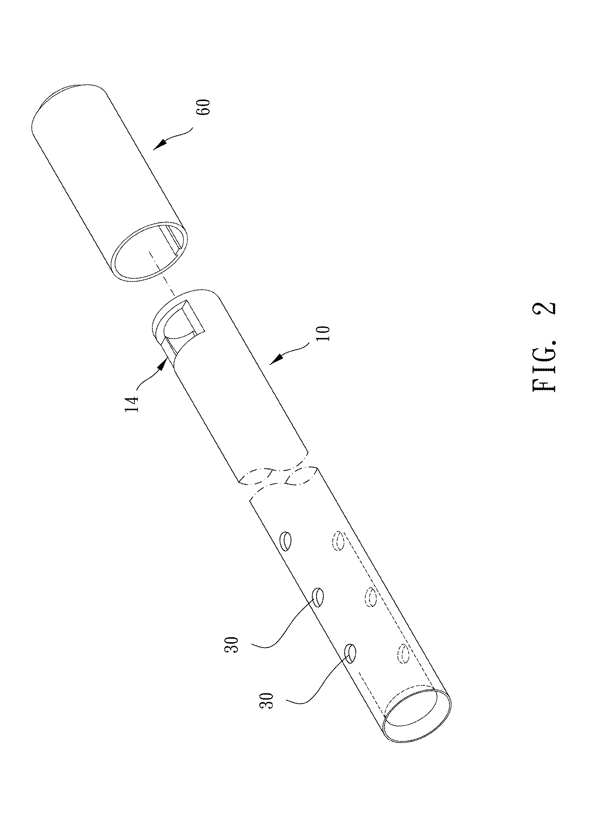
[0007]The major object of the present invention is to provide a gun barrel for guiding an air flow inside the gun barrel to make a bullet member fly stably. In addition, a number, a distance and an arrangement of vent holes may be adjusted for cooperating with various gun barrel structure

Problems solved by technology

However, the gun barrel structure mentioned above does not have a structure for guiding and positioning the bullet member, so the preciseness and stability need to be improved.
For example, when the bullet member enters the gun barrel and is pressed by the two protruding ribs, the position and direction of the bullet member may deviate so that the bullet member is unable to move smoothly in the gun barrel.

Method used


Image

  • Gun barrel
  • Gun barrel
  • Gun barrel

Examples


fourth embodiment

[0029]Please refer to FIG. 8 for the present invention. A plurality of vent holes 30c are arranged around the circumferential face of the barrel body 10 on a radial plane of the barrel body 10. More specifically, viewed from an axial direction of the barrel body 10, the vent holes 30c are angularly spaced and annularly disposed along the axial direction of the barrel body 10 for guiding the air flow in the barrel body 10.

fifth embodiment

[0030]Please refer to FIG. 9 for the present invention. A plurality of vent holes 30d located on two opposite sides of the barrel body 10 are crossedly arranged. Preferably, when the bullet member 40 passes through the vent holes 30d which are crossedly arranged, pressures of two opposite sides of the bullet member 40 are different so as to make the bullet member 40 spin and make the shot range farther and the shooting effect preferable

sixth embodiment

[0031]Please refer to FIGS. 10 and 11 for the present invention, a barrel body 10a further includes at least one blind guiding slot 70 disposed between the bullet outlet 13 and a vent hole 30e. The blind guiding slot 70 is recessed on a circumferential face of the barrel body 10a. An end of the blind guiding slot 70 is communicated with the vent hole 30e, and the other end of the blind guiding slot 70 extends to a distal side of the bullet outlet 13 and is communicated with outside. The vent hole 30e is axially elongate and trapped radially inward, and the blind guiding slot 70 is axially elongate and aligned with the vent hole 30e axially. Preferably, when an air flow in the barrel body 10a flows outward through the vent hole 30e, the blind guiding slot 70 is provided for guiding the air flow to flow along the blind guiding slot 70 to outside so as to elevate the effect of ventilation.

[0032]Given the above, a gun barrel of the present invention is provided for guiding the air flow ...


PUM


Abstract

A gun barrel is provided, including: a barrel body, having a passage therethrough, the passage being provided for a bullet member to be received and pass therethrough, two opposite ends of the passage of the barrel body being respectively formed with a bullet inlet and a bullet outlet formed by an inner wall of the barrel body surroundingly and continuously arranged, a circumferential face of the barrel body being formed with an opening, the opening being near the bullet inlet; a tangential portion, disposed at the opening restrictedly and partially movably protrusive into the passage, the tangential portion for providing friction with a surface of the bullet member tangentially; at least one vent hole, disposed through the barrel body and being near the bullet outlet.

Description

BACKGROUND OF THE INVENTION[0001]1. Field of the Invention[0002]The present invention relates to a tube member, and more particularly to a gun barrel.[0003]2. Description of the Prior Art[0004]Usually, a conventional gun barrel structure as disclosed in TWM480667 at least includes a barrel body, and two sides of the barrel body have an opening respectively. One of the openings is a conic opening tapered inward, and the other end of the openings is formed with two protruding ribs. A gun barrel can be put into the barrel body and push a bullet member through high pressure air. The bullet member is pressed by the two protruding ribs to produce a great tangential force so as to make the bullet member spin.[0005]However, the gun barrel structure mentioned above does not have a structure for guiding and positioning the bullet member, so the preciseness and stability need to be improved. For example, when the bullet member enters the gun barrel and is pressed by the two protruding ribs, th...

Claims


Application Information

Patent Timeline
IPC IPC(8): F41A21/28
CPCF41A21/28F41A21/16
Inventor XU, YOU-RUI
Owner XU YOU RUI
Why Eureka
Try Eureka