Method for securing a securing clamp on a cable of an overhead transmission line, manipulator and securing clamp

a technology of overhead transmission lines and clamps, applied in the direction of suspending electric cables, maintaining distance between parallel conductors, devices for damping mechanical oscillations, etc., can solve the problem that existing transmission lines are often only accessible with effort, and achieve the effect of much easier installation

Active Publication Date: 2016-11-24
RICHARD BERGNER VERBINDUNGSTECHN
View PDF6 Cites 10 Cited by
  • Summary
  • Abstract
  • Description
  • Claims
  • Application Information

AI Technical Summary

Benefits of technology

[0013]In an exemplary embodiment, a method is provided for securing a securing clamp on a cable, in particular a transmission line. For this purpose, a manipulator can be and preferably is provided, by means of which a respective securing clamp is automatically secured to the cable, i.e., mechanically, without any manual actuation of the securing clamp by a technician being required. The manipulator can comprise an assembly mechanism, which is designed for the automatic assembly and operation of the securing clamp. By means of the automated attachment, the assembly effort is considerably less, since, firstly, a respective technician no longer needs to access the cable. It is therefore no longer required in the open field that operating personnel manually secure the individual objects to the cables of the transmission line. Especially with a live power line, this is of particular advantage. Firstly, because in particular, existing transmission lines are accessible often only with effort. Furthermore, installation can also be done in a live state by means of the manipulator without requiring a shutdown of the live transmission line.
[0039]In an embodiment, the two brackets are elastic, in particular via a spring element, clamped against one another, wherein the spring effect is oriented in the closing direction, i.e., so that by using the spring, the two brackets can be reliably held in the closed position.

Problems solved by technology

Firstly, because in particular, existing transmission lines are accessible often only with effort.

Method used


Image

  • Method for securing a securing clamp on a cable of an overhead transmission line, manipulator and securing clamp
  • Method for securing a securing clamp on a cable of an overhead transmission line, manipulator and securing clamp
  • Method for securing a securing clamp on a cable of an overhead transmission line, manipulator and securing clamp

Examples


Embodiment Construction

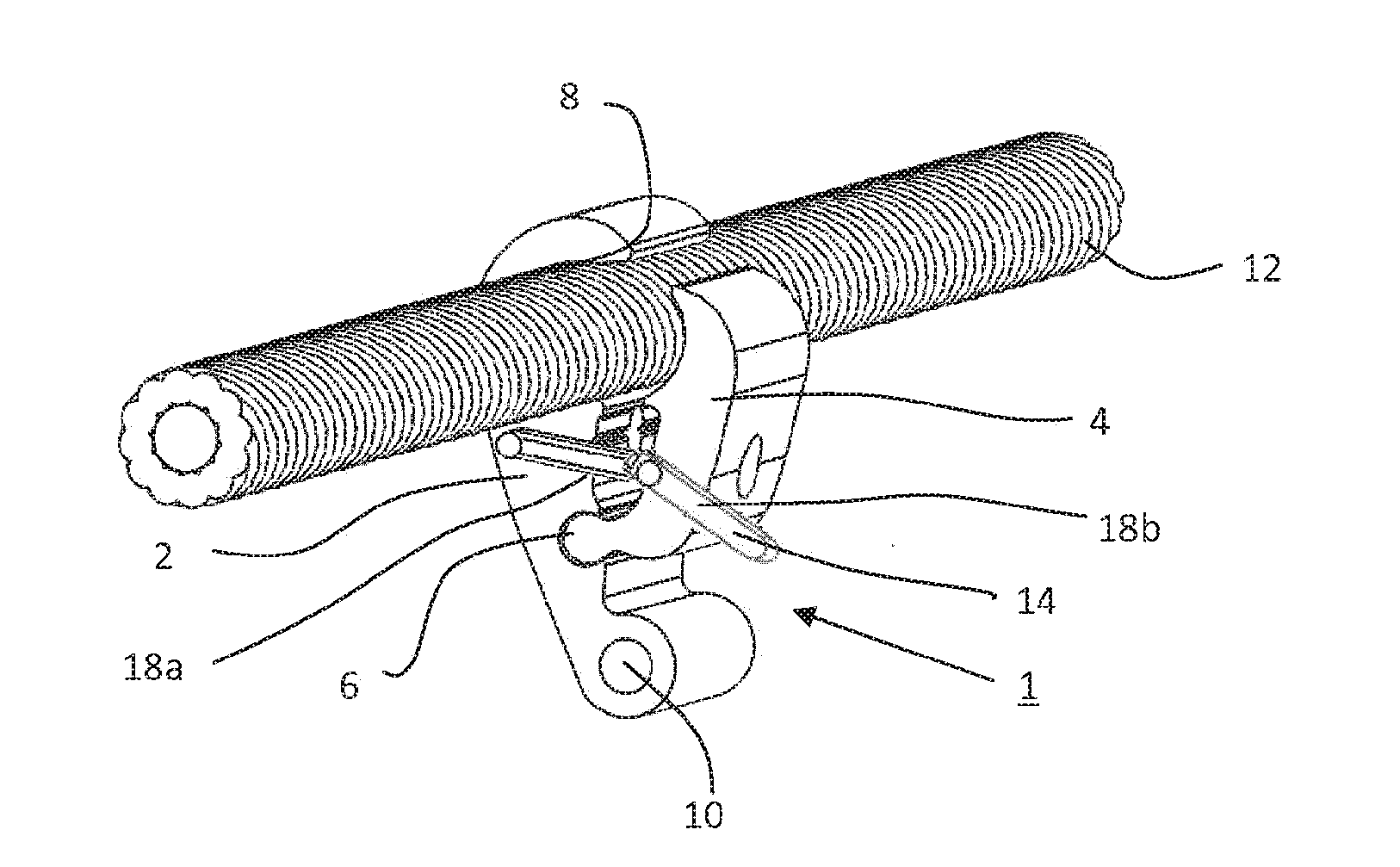
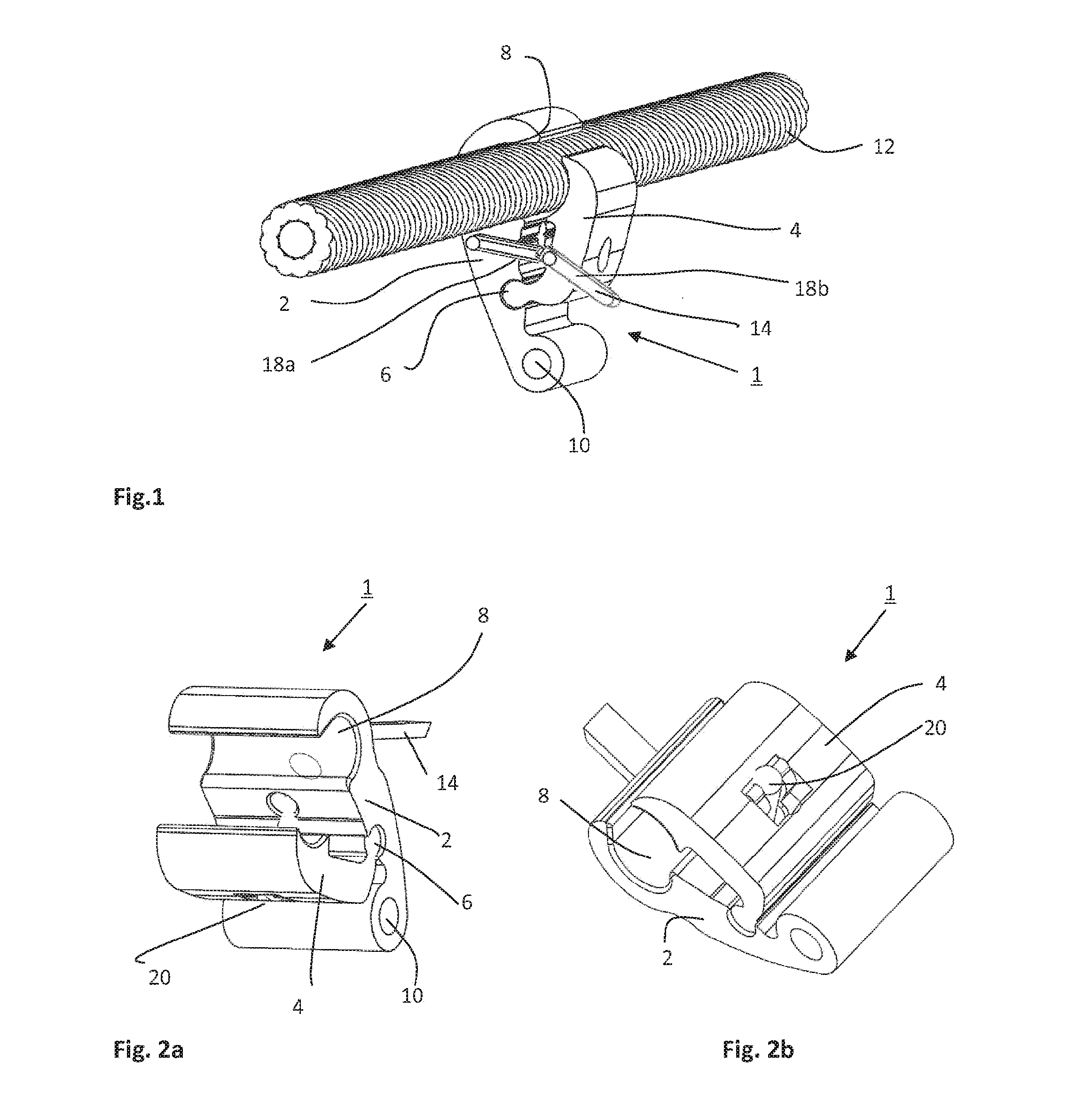
[0054]The securing clamp 1 has a main bracket 2 and a closing bracket 4, which at a first swivel joint 6 is pivotally mounted on the main bracket 2. The two brackets 2, 4 are, for example, a continuous casting profile, particularly in the embodiments according to the FIGS. 1, 2a, 2b, 7a, 7b. The two brackets 2, 4 are clamped against one another without screws. The main bracket 2 generally has at one end a hook or claw-shaped cable receiving 8 and at its opposite end, a securing element formed in the embodiments as a mounting lug 10. At this end opposite the cable receiving 8, an object 50 to be fixed on the cable 12 is attached to the securing clamp 1.

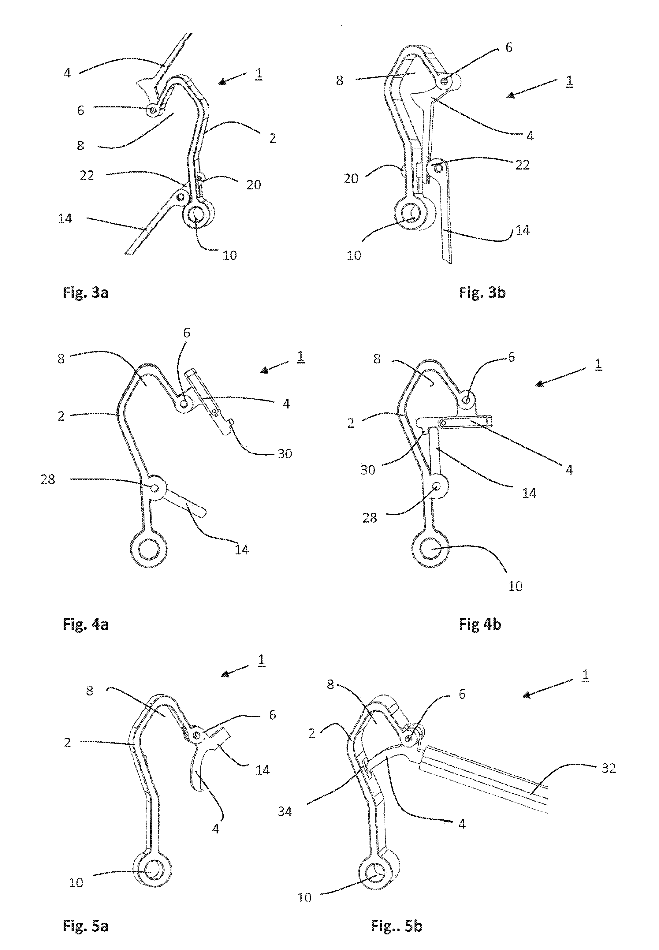
[0055]The embodiments of FIGS. 3 to 6 each show an embodiment with a main bracket 2 which is designed relatively elongated and with a pronounced, hook-shaped cable receiving 8. These embodiments can be hung particularly easily on the cable 12. In the embodiments of FIGS. 1, 2 and 7, the main bracket 2 is formed more compact and has a l...


PUM

PropertyMeasurementUnit
heightaaaaaaaaaa
movementaaaaaaaaaa
electrical poweraaaaaaaaaa

Abstract

A method for securing a securing clamp to a cord or a freeline. The securing clamp is automatically secured to the cord using a maniplulator, the manipulator has an assembly mechanism that is used to secure the securing clamp to the cord. The securing clamp has two brackets which can be adjusted relative to each other and which can be converted from an open position into a closed position, i.e. the cord-clamping position. The two brackets can be clamped against each other without screws for a simple assembly, and the securing clamp further has an actuating mechanism via which the two brackets can be converted from the open position into the closed position. To convert the position of the brackets, an actuating arm simply needs to be folded over or a blocking element simply needs to be removed. This is carried out automatically using the assembly mechanism of the manipulator.

Description

[0001]This nonprovisional application is a continuation of International Application No. PCT / EP2015 / 052235, which was filed on Feb. 4, 2015, and which claims priority to German Patent Application No. 10 2014 201 999.0, which was filed in Germany on Feb. 4, 2014, and which are both herein incorporated by reference.BACKGROUND OF THE INVENTION[0002]Field of the Invention[0003]The invention relates to a method for securing a securing clamp on a cable, in particular an overhead transmission cable. The invention further relates to a manipulator and a securing clamp for securing on a cable.[0004]Description of the Background Art[0005]In transmission lines, usually transmission line cables are stretched between, for example, anchor points formed by masts. The transmission lines in this respect are conductors for transporting electrical power, but may also be data cables. The anchor points are often spaced several hundred meters apart. Because of this large spacing, it is required that for p...

Claims


Application Information

Patent Timeline
Patent Type & Authority Applications(United States)
IPC IPC(8): H02G7/08H02G7/14
CPCH02G7/08H02G7/14Y10T29/49826H02G7/12
Inventor MURR, MANFRED
Owner RICHARD BERGNER VERBINDUNGSTECHN
Why Eureka
Try Eureka