
Rotor Assembly and Motor Including the Same

a rotor and motor technology, applied in the direction of magnetic circuits, magnetic circuits, rotating parts, etc., can solve the problems of foreign material generation, magnetic loss, magnets that cannot be fixed, etc., and achieve the effect of reducing magnetic loss

Active Publication Date: 2016-12-01
LG INNOTEK CO LTD
View PDF5 Cites 4 Cited by
  • Summary
  • Abstract
  • Description
  • Claims
  • Application Information

AI Technical Summary

Benefits of technology

The present invention proposes a way to reduce magnetic loss during bonding using an adhesive. This is achieved by adding a layer of adhesive material containing ferromagnetic powder between the magnet and the magnet insertion hole. The technical effect is to significantly reduce the energy required for the magnetic bond.

Problems solved by technology

However, in such a fixing method, when a motor is used for a long time or is used for a long time at a high temperature, since adhesive strength of the adhesive which fixes the magnet becomes weak, there are problems of the magnet moving from an original mounting position, foreign material being generated due to separation of the adhesive, and a magnet that cannot be fixed due to a glass transition phenomenon at a high temperature.
Particularly, for adhesive fixing of the magnet, a region which is not filled with the adhesive occurs in the magnet insertion hole, and such a region leads to magnetic loss.

Method used


Image

  • Rotor Assembly and Motor Including the Same
  • Rotor Assembly and Motor Including the Same
  • Rotor Assembly and Motor Including the Same

Examples


Embodiment Construction

[0023]Hereinafter, a structure and an operation according to the present invention will be specifically described. In the description with reference to accompanying drawings, the same components are assigned with the same reference numerals regardless of drawing numerals and repetitive descriptions thereof will be omitted. While such terms as “first,”“second,” etc., may be used to describe various components, such components must not be limited to the above terms. The above terms are used only to distinguish one component from another.

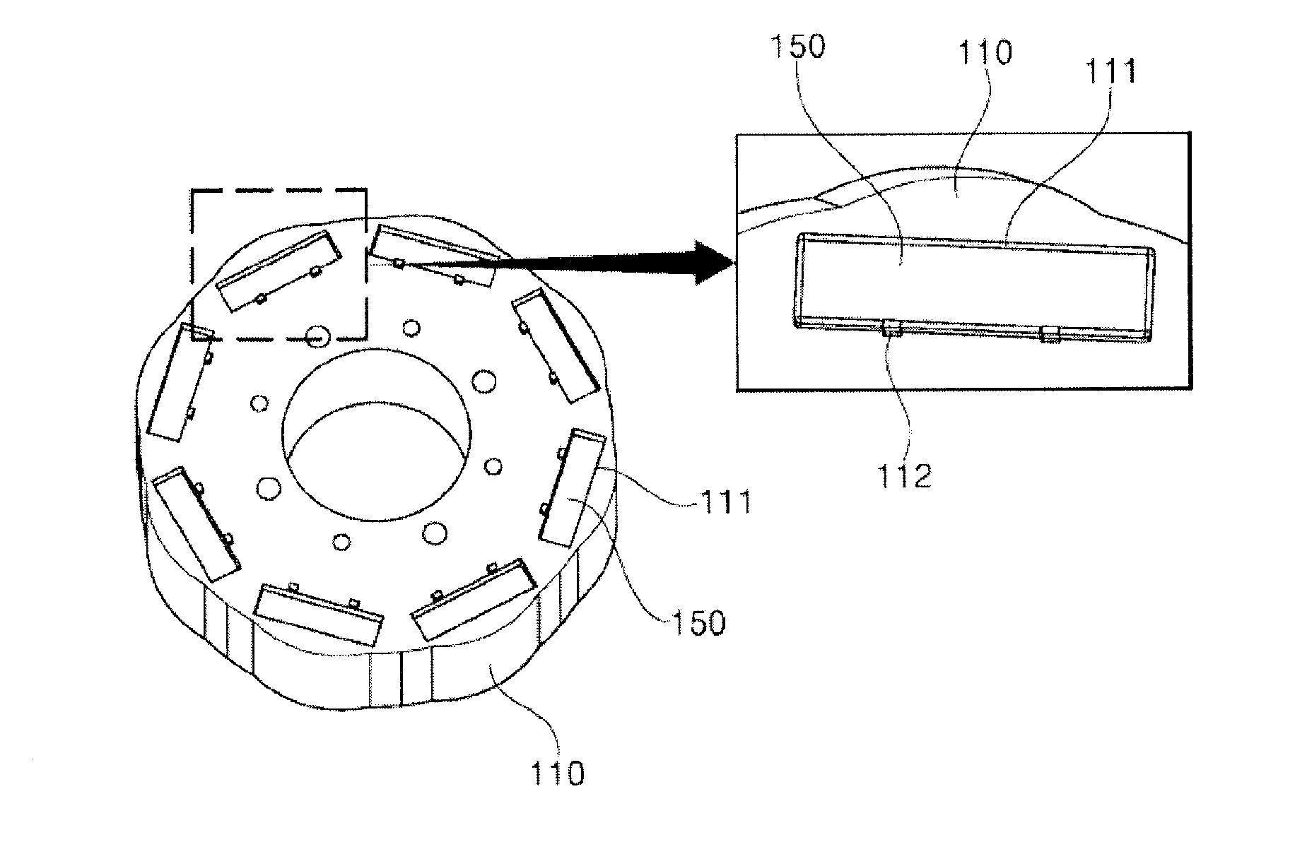
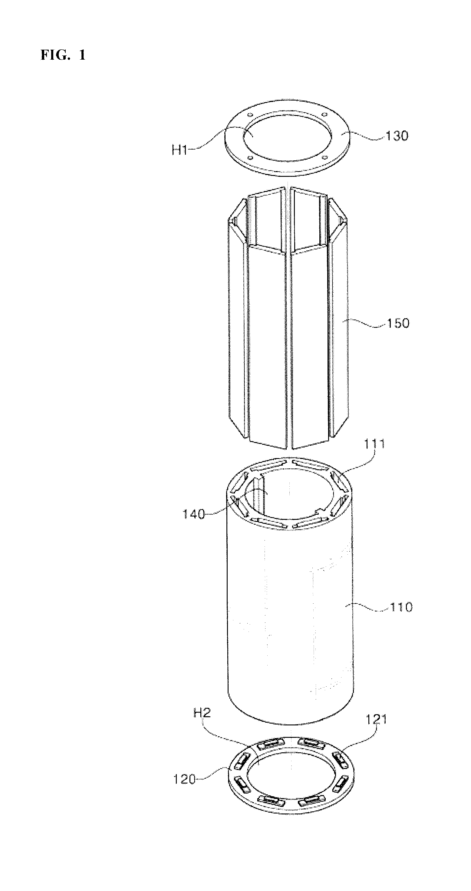
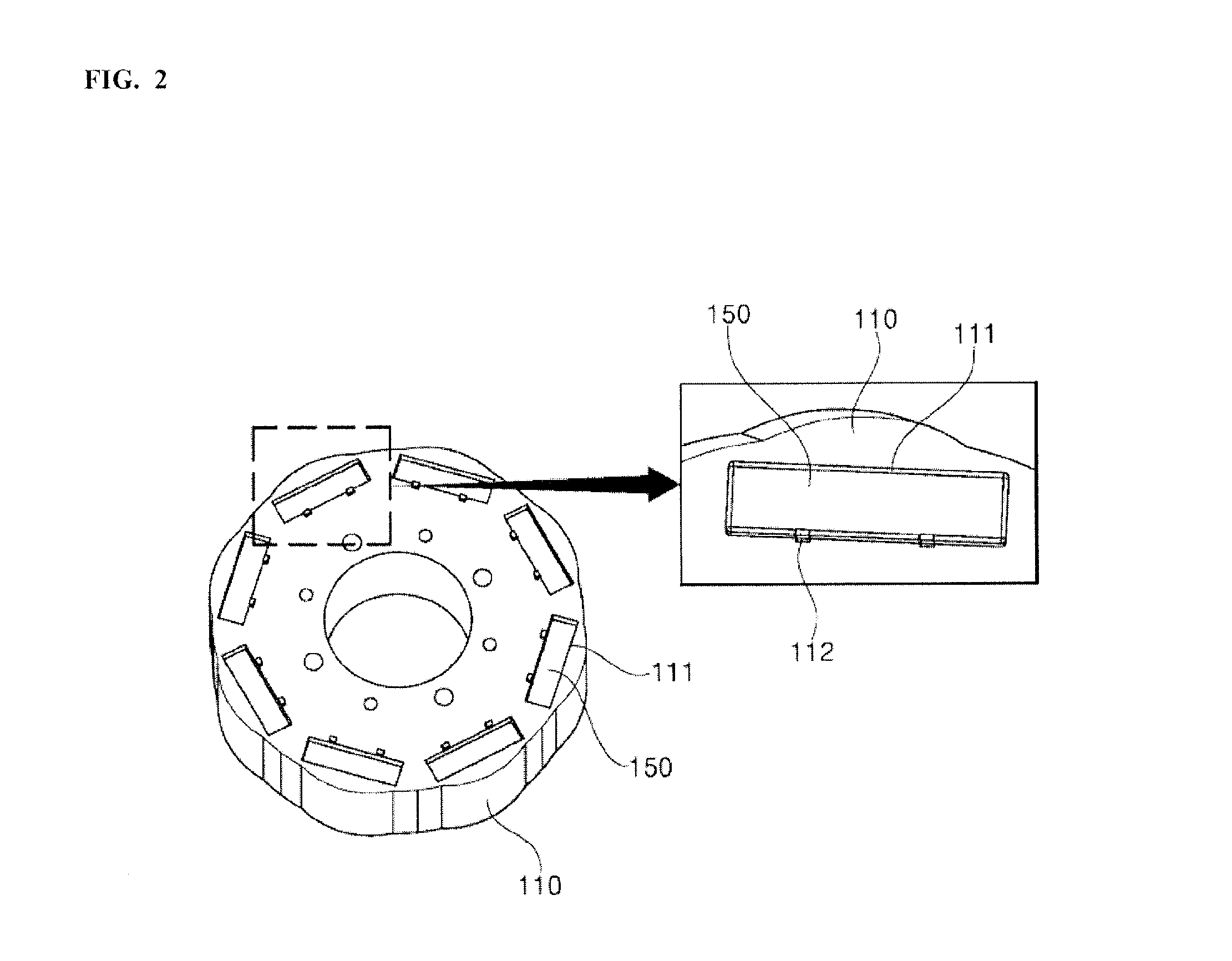
[0024]FIG. 1 is a conceptual view for describing a structure of rotor assembly according to an embodiment of the present invention,FIG. 2 is an exploded conceptual view illustrating a main portion of the rotor shown in FIG. 1, and FIG. 3 is a table illustrating a result of applying a ferromagnetic bonding layer according to the embodiment of the present invention.

[0025]Referring to FIGS. 1 and 2, a rotor 100 according to the embodiment of the present i...


PUM


Abstract

The present invention relates to a motor for a vehicle and a rotor applied to the motor, and the rotor may include a rotor housing including a magnet mounting portion; a magnet inserted in the magnet mounting portion; and a ferromagnetic bonding layer which fills between the magnet mounting portion and the magnet.

Description

CROSS-REFERENCE TO RELATED APPLICATION[0001]This application claims the benefit under 35 U.S.C. §119 of Korean Patent Application No. 10-2015-0074105, filed May 27, 2015, which is hereby incorporated by reference in its entirety.TECHNICAL FIELD[0002]Embodiment of the present invention relates to a motor for a vehicle and a rotor applied to the same.BACKGROUND ART[0003]As motors for vehicles gradually evolve into ones with high torque and high speed specifications, a robust design for a rotor assembly structure applied to a motor is becoming essential.[0004]Generally, a structure of a rotor applied to an interior permanent magnet (IPM) motor is formed by forming a stacked rotor core which is formed by stacking a plurality of rotor core members in a disk shape and inserting a magnet in the rotor core.[0005]Here, the magnet inserted in the rotor core is fixedly adhered to the magnet insertion hole using an adhesive and the like. However, in such a fixing method, when a motor is used fo...

Claims


Application Information

Patent Timeline
Patent Type & Authority Applications(United States)
IPC IPC(8): H02K1/28H02K1/27
CPCH02K1/276H02K1/28H02K1/02H02K2213/03Y02T10/64
Inventor KIM, BYEONG YONGKIM, YONG CHUL
Owner LG INNOTEK CO LTD
Learn More