Core for Stationary Induction Apparatus
a stationary induction and core technology, applied in the direction of transformer/inductance details, electrical apparatus, magnetic cores of transformers/inductances, etc., can solve the problems of stray loss, increased magnetic loss due to load, and difficulty in self-standing, and achieve low magnetic loss and high mechanical strength.
- Summary
- Abstract
- Description
- Claims
- Application Information
AI Technical Summary
Benefits of technology
Problems solved by technology
Method used
Image
Examples
example 1
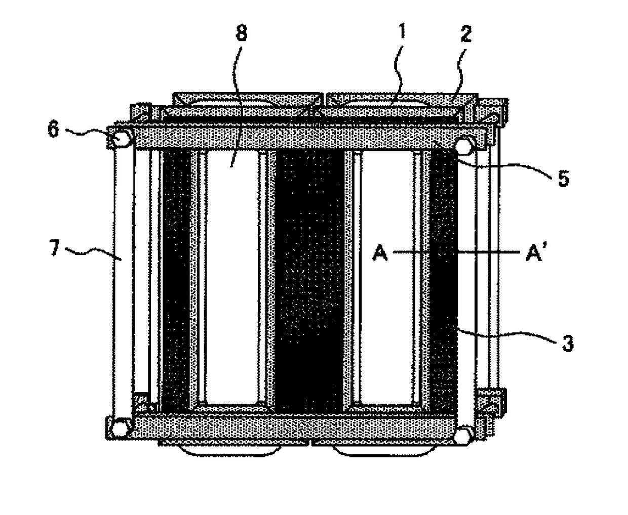
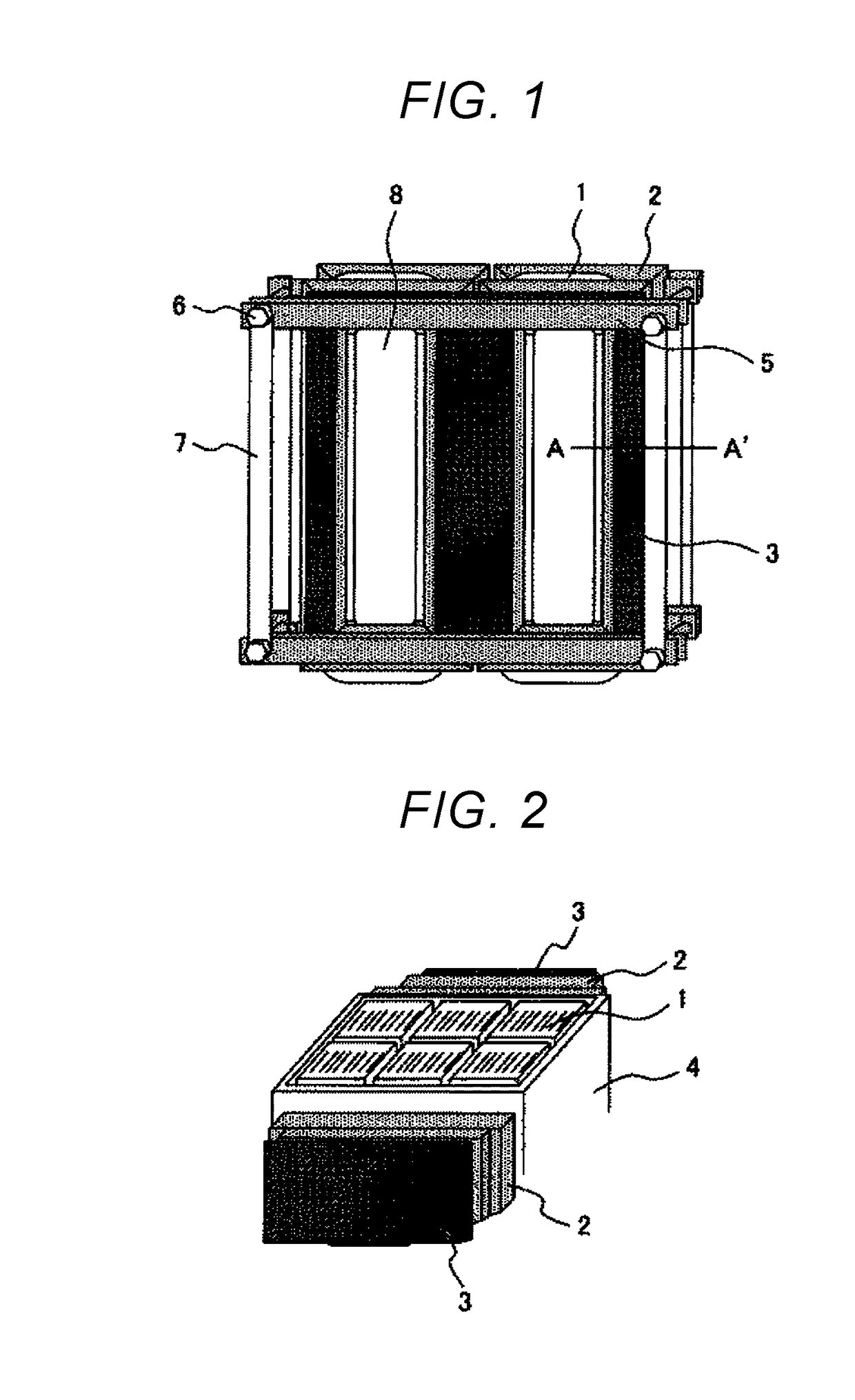
[0023]FIG. 1 and FIG. 2 show Example 1 of a core fora stationary induction apparatus of the invention.
[0024]As shown in the figures, the core for a stationary induction apparatus of the present example schematically includes an amorphous core 1 formed of an amorphous thin magnetic strip arranged inside the core, a silicon steel sheet core 2 formed of a silicon steel sheet arranged on both sides (both side surfaces) of the amorphous core 1, a wear plate 3 arranged on the outermost peripheral surface of the silicon steel sheet core 2, an amorphous core frame 4 arranged around the amorphous core 1 including a space between the amorphous core 1 and the silicon steel sheet core 2, and a support frame 5 which supports and fixes the amorphous core 1 and the silicon steel sheet core 2 via the wear plate 3 by clamping them with a clamping jig (for example, a bolt) 6.
[0025]The support frame 5 is arranged in a transverse direction on an upper portion and a lower portion of an outer peripheral ...
example 2
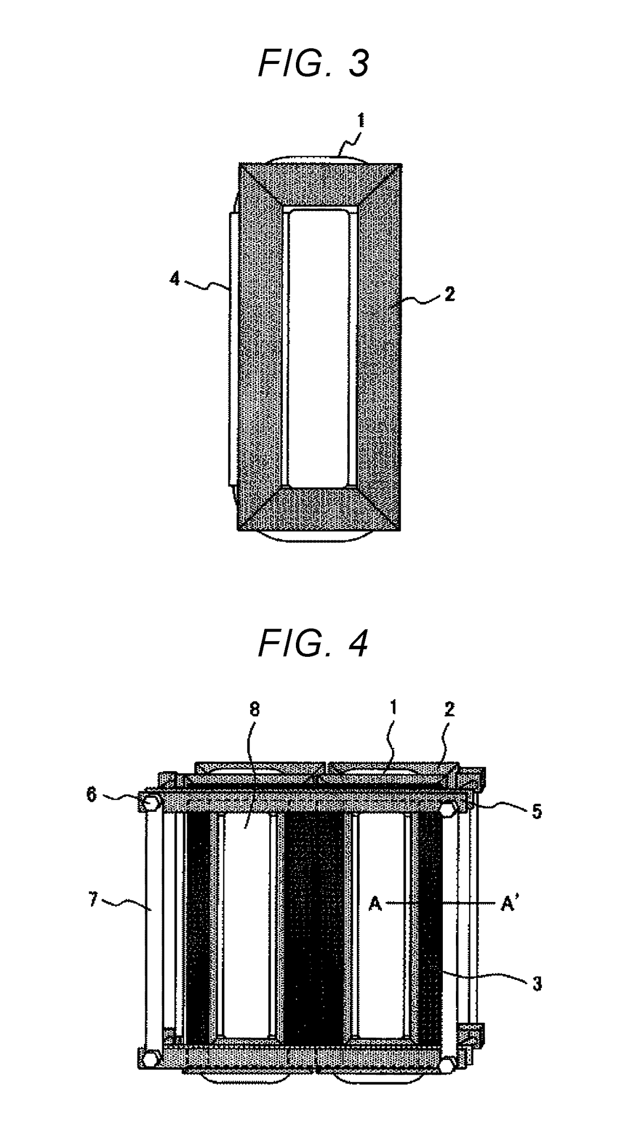
[0036]FIG. 4 shows Example 2 of a core for a stationary induction apparatus of the invention.
[0037]The core for a stationary induction apparatus of the example shown in the figure is one in which the shape of the wear plate 3 arranged between the silicon steel sheet core 2 and the support frame 5 is modified in the configuration described in Example 1.
[0038]That is, as shown in FIG. 4, the wear plate 3 is divided into a plurality of pieces (8 in this example) in the example, and by using the divided wear plate 3, operation at the time of assembly becomes easy because the size of the wear plate 3 per piece can be reduced.
[0039]The wear plate 3 may be made of iron, and it may also be made of a nonmagnetic material such as SUS, Al, wood and a resin. When the wear plate 3 is made of iron, an eddy current loss due to interlinkage flux is reduced by inserting a slit in the wear plate 3, and thus heat generation of the wear plate 3 can be prevented.
[0040]Since the support frame 5 is config...
example 3
[0042]FIG. 5 and FIG. 6 show Example 3 of a core for a stationary induction apparatus of the invention.
[0043]The core for a stationary induction apparatus of the example shown in the figures is one in which silicon steel sheets are stacked and the width of the silicon steel-stacked block core 2 where a step-lap joint structure is formed at a corner is modified in the configuration described in Example 1.
[0044]That is, the silicon steel-stacked block core 2 is configured such that the width decreases sequentially from the amorphous core 1 side toward the wear plate 3 side.
[0045]By the configuration of the example, it is not only possible to obtain the same effect as in Example 1, but also possible to make the cross section of the core into an approximately circular shape, to arrange the core in a circular winding without waste and to increase winding space factor of the core.
[0046]In addition, it may also be configured that only the yoke part of the silicon steel sheet core 2 is a pl...
PUM
 Abstract
Description
Claims
Application Information
 - R&D
- Intellectual Property
- Life Sciences
- Materials
- Tech Scout
- Unparalleled Data Quality
- Higher Quality Content
- 60% Fewer Hallucinations
Browse by: Latest US Patents, China's latest patents, Technical Efficacy Thesaurus, Application Domain, Technology Topic, Popular Technical Reports.
© 2025 PatSnap. All rights reserved.Legal|Privacy policy|Modern Slavery Act Transparency Statement|Sitemap|About US| Contact US: help@patsnap.com


