Vibration actuator that is easy in conduction inspection

a technology of vibration actuator and conduction hole, which is applied in piezoelectric/electrostrictive/magnetostrictive devices, piezoelectric/electrostriction/magnetostriction machines, electrical apparatus, etc., can solve the problem of not being able to confirm whether or not sufficient conductivity is obtained in through holes, and achieves the effect of easy inspection of conductivity

Active Publication Date: 2016-12-08
CANON KK
View PDF4 Cites 0 Cited by
  • Summary
  • Abstract
  • Description
  • Claims
  • Application Information

AI Technical Summary

Benefits of technology

[0007]The present invention provides a vibration actuator that enables easy inspection of conductivity of a co

Problems solved by technology

However, the conventional configuration using a through hole has a problem that it is impossible to confirm whether or not

Method used


Image

  • Vibration actuator that is easy in conduction inspection
  • Vibration actuator that is easy in conduction inspection
  • Vibration actuator that is easy in conduction inspection

Examples


Embodiment Construction

[0032]The present invention will now be described in detail below with reference to the accompanying drawings showing embodiments thereof.

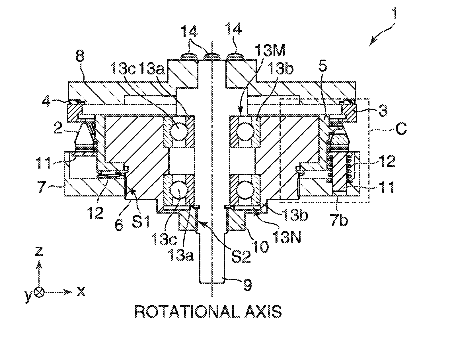
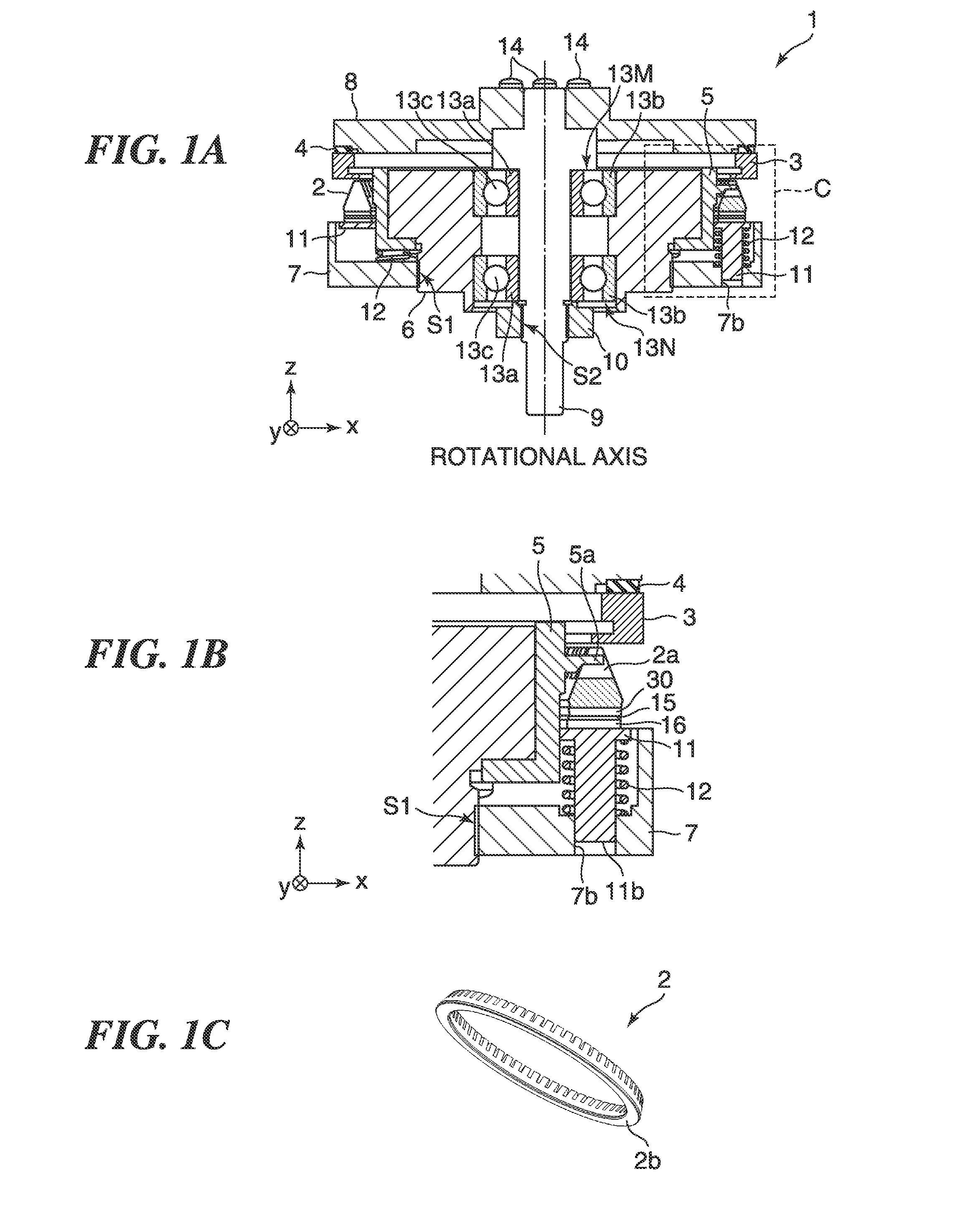
[0033]FIG. 1A is a schematic cross-sectional view of a vibration actuator 1 according to an embodiment of the present invention. FIG. 1B is an enlarged cross-sectional view of an area C surrounded by a broken line in FIG. 1A. FIG. 1C is a perspective view of an elastic body 2 as a component of the vibration actuator 1. As to the configuration of the vibration actuator 1, an x direction, a y direction, and a z direction, which are orthogonal to each other, are defined as shown in FIG. 1A, for convenience' sake.

[0034]The vibration actuator 1 includes the elastic body 2, a driven element 3, an anti-vibration rubber 4, a rotation stopping member 5, a housing 6, a supporting member 7, a flange 8, an output shaft 9, a preload member 10, a pressing member 11, coil springs 12, rolling bearings 13M and 13N, fastening members 14, a nonwoven fabric 16, and a...


PUM


Abstract

A vibration actuator that enables easy inspection of conductivity of a conduction path for connecting an electrode of an electromechanical energy conversion element to a GND potential. In the vibration actuator, a vibration element includes an elastic body formed of a material which is insulating, dielectric, or semi-conductive, and a piezoelectric element joined to the elastic body. The piezoelectric element includes a first electrode formed on a surface of a piezoelectric body via which surface the piezoelectric body is joined to the elastic body, a second electrode provided in a manner opposed to the first electrode via the piezoelectric body, and at least two conduction paths each having a conductor in a through hole formed in the piezoelectric body. One of the at least two conduction paths electrically connects the first electrode and the second electrode.

Description

BACKGROUND OF THE INVENTIONField of the Invention[0001]The present invention relates to a vibration actuator easy in conduction inspection, which brings a vibration element and a driven element into pressure contact with each other and excites vibration in the vibration element to thereby move the vibration element and the driven element relative to each other.Description of the Related Art[0002]A vibration actuator using an electromechanical energy conversion element represented e.g. by a piezoelectric element uses a friction force acting between a vibration element formed by joining the electromechanical energy conversion element to an elastic body and a driven element, and performs driving for moving the vibration element and the driven element relative to each other. Therefore, the vibration actuator is capable of generating a high thrust or torque in a low-speed region, and has high responsiveness, and hence the vibration actuator can be used as a driving source of a precision ...

Claims


Application Information

Patent Timeline
IPC IPC(8): H02N2/00H01L41/047
CPCH01L41/0475H02N2/001H02N2/00H02N2/163H10N30/875
Inventor ARIMITSU, YASUMICHI
Owner CANON KK
Why Eureka
Try Eureka