Tool Stand With Automatically Deployable Legs

Active Publication Date: 2016-12-22
AFFINITY TOOL WORKS
View PDF4 Cites 12 Cited by
  • Summary
  • Abstract
  • Description
  • Claims
  • Application Information

AI Technical Summary

Benefits of technology

[0006]In general terms, the tool stand of the present invention provides a relatively compact tool stand that is easily transported to and from jobsites. The tool stand can fit in a fairly small space in a vehicle and can be easily carried to the jobsite. In

Problems solved by technology

The difficulty with typical tool stands is that they can be large and unwieldy.
If the legs are fixed in place,

Method used


Image

  • Tool Stand With Automatically Deployable Legs
  • Tool Stand With Automatically Deployable Legs
  • Tool Stand With Automatically Deployable Legs

Examples


Embodiment Construction

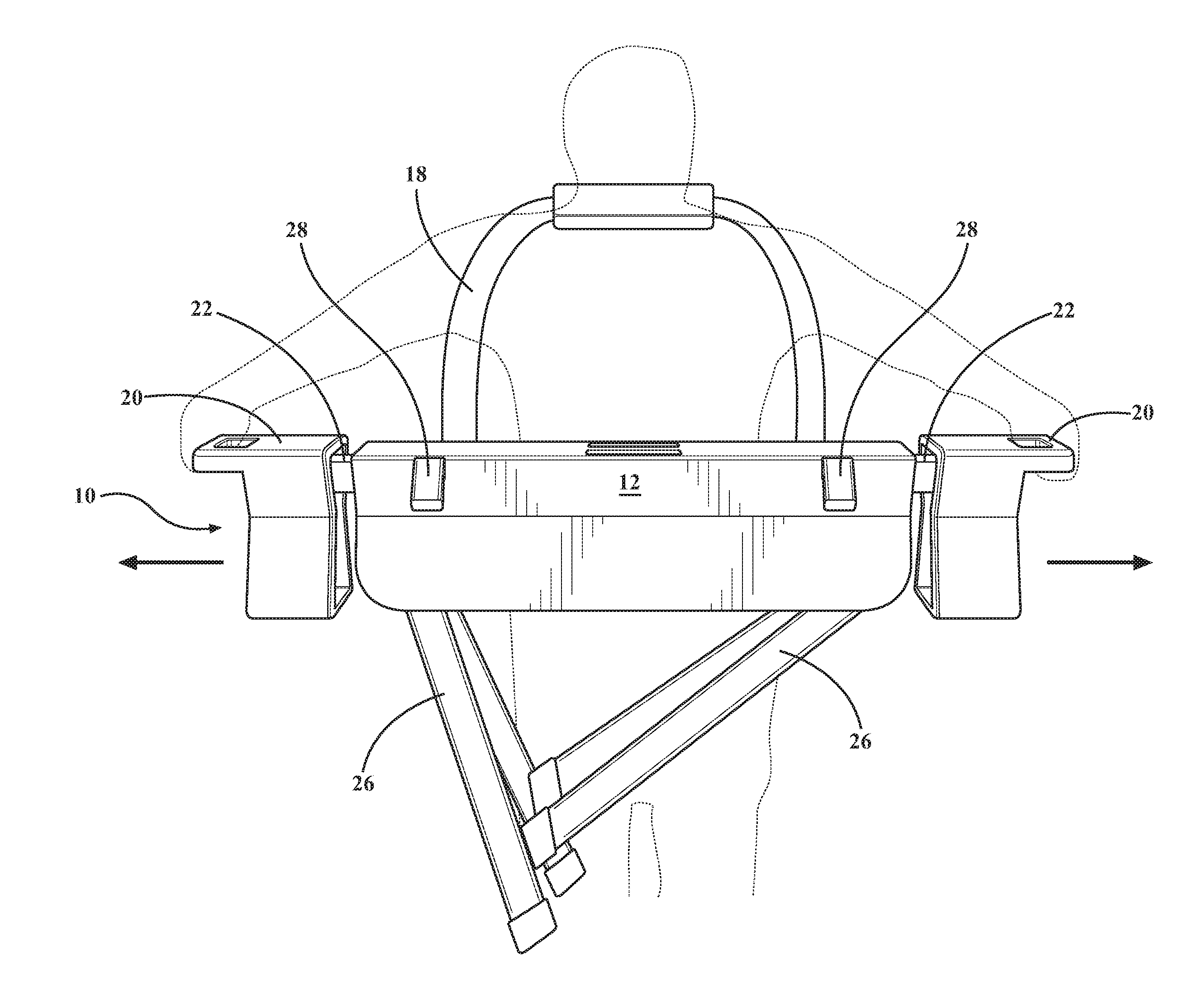
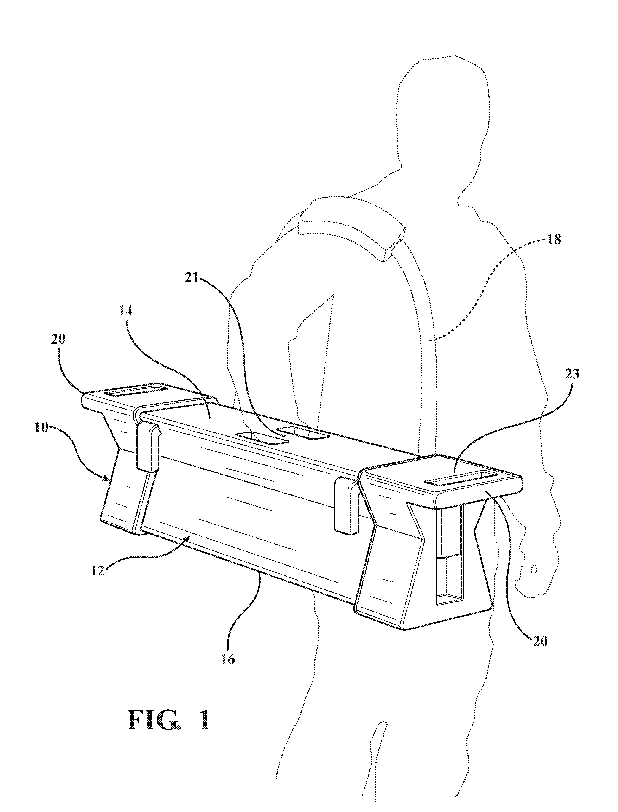
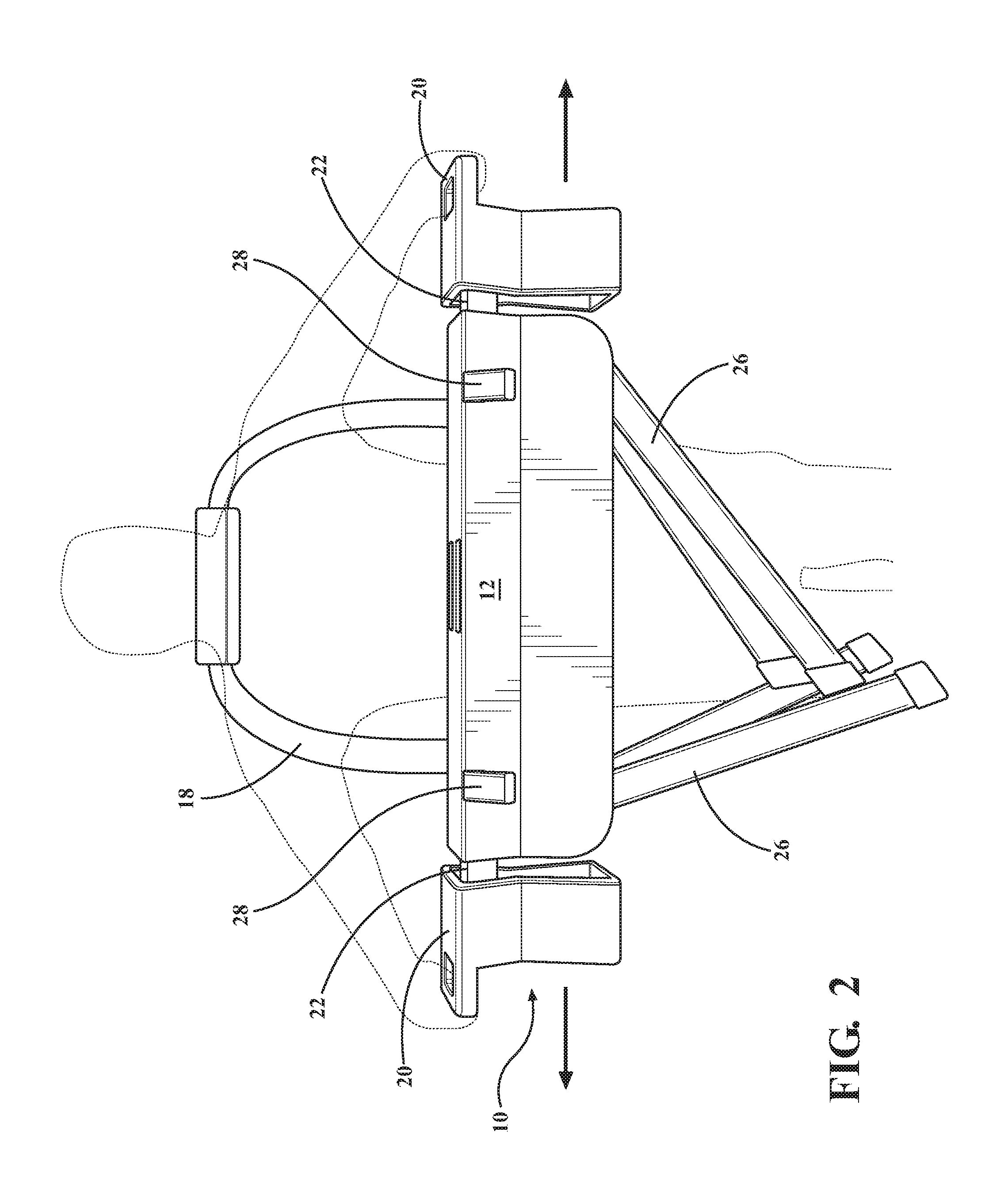
[0017]The portable tool stand of the present invention is shown generally at 10 in FIGS. 1 through 4. The tool stand 10 has a body portion 12 with a generally flat top 14 and a bottom surface 16. As illustrated, the bottom surface 16 is generally flat to allow the tool stand to be stored on a generally flat surface. A strap 18 is provided to carry the tool stand 10. Additionally, in the disclosed embodiment, a handgrip 21 is provided to allow the tool stand 10 to be carried by the hand grip 21 in the top 14. As illustrated, the hand grip 21 is formed by an opening in the top 14 with the hand grip 21 spanning that opening.

[0018]Handles and material supports 20 are provided on opposed sides of the body portion 12. The handles 20 are mounted on arms 22 that can slide with respect to body portion 12. The handles 20 can be extended to create a work surface that is wider than the width of the body portion 12. The handles 20 can also be moved perpendicular to the arms 22 to raise the top s...


PUM


Abstract

A portable tool stand having automatically deployable legs. The tool stand has a body with a work surface and opposed ends. Deployable legs are pivotally mounted to the tool stand. The legs move between a stored position adjacent to the body and a support position wherein the legs are deployed to support the body. Retractable arms are mounted to each end of the body and slide with respect to the body. The deployable legs and the arms are operably connected such that sliding the arms with respect to the body moves the legs between the stored position and the support position.

Description

CROSS REFERENCE TO RELATED APPLICATION[0001]This application claims the benefit of U.S. Provisional Application No. 62 / 111,264 filed Feb. 3, 2015, which is incorporated herein by reference in its entirety.BACKGROUND OF THE INVENTION[0002]The present invention generally relates to tool support stands. Tool support stands are well known and generally employ a work surface to which a tool, such as a saw, can be mounted and legs to support the stand. These tool support stands come in any number of sizes and shapes, but typically have four legs that are fixed in the support position or can be individually folded or telescoped to a closed position. Some of these known work tables also include extendable work surfaces that can be pulled out to make the overall length of the tool stand longer.[0003]Examples of applicant's tool stands can be found in United States Design Pat. Nos. D623,672 and D549,749.[0004]The difficulty with typical tool stands is that they can be large and unwieldy. If t...

Claims


Application Information

Patent Timeline
IPC IPC(8): B25H1/04A47B3/08A45F3/14
CPCB25H1/04A45F2003/142A47B3/08A45F3/14B25H1/06
Inventor URSELL, MIKEURSELL, CONNORCROSS, MARKURSELL, SAMNEILSON, KEN
Owner AFFINITY TOOL WORKS
Why Eureka
Try Eureka