Cockpit seat armrest avionics cursor control device

a cursor control device and armrest technology, applied in the direction of actuating personally, aircraft crew accommodation, seating arrangements, etc., can solve the problems of consuming premium space, affecting and the current ccd design is bulky and unsuitable for typical desktop computer input devices. , to achieve the effect of improving pilot ingress and egress

Inactive Publication Date: 2016-12-22
AERION INTPROP MANAGEMENT CORP
View PDF1 Cites 6 Cited by
  • Summary
  • Abstract
  • Description
  • Claims
  • Application Information

AI Technical Summary

Benefits of technology

[0006]The present invention concerns an avionics cursor control device that, unlike existing designs, simultaneously provides for excellent arm and hand support, carries controls configured and positioned for instant finger feel recognition of aircraft control function or functions, does not occupy space on the center pedestal or on the cockpit sidewalls or side consoles, and is within easy reach of each pilot without interfering with other cockpit controls, and is retractable for improved pilot ingress and egress. These position advantages are gained by integrating the CCD with the adjustable pilot seat armrest.
[0007]The seat armrest location follows the pilot's longitudinal and vertical seat adjustments and is therefore always in the ideal location for the comfortable placement of the arm and wrist. At the forward end of the armrest, arranged to be easily within reach of the pilot's fingers, with the wrist at a comfortable rest state, are the various input controls such as buttons, knobs, scroll wheels, joysticks, track balls, touch-sensitive or multi-touch surfaces. The armrest is preferably attached to the seat in such a way that it can be retracted or folded out of the way. A hinge may be employed at the aft end of the armrest to allow the armrest to be rotated upwardly to align parallel with and in the same geometric plane with the back of the seat.

Problems solved by technology

Due to human factor requirements of having to interact with cockpit avionics while the aircraft is in motion, such as while maneuvering or bouncing while taxiing or while flying through turbulence, typical desktop computer input devices are often inappropriate.
Current CCD designs are bulky, and consume premium space either on the center pedestal between pilot seats, or on the sidewalls, or side consoles, outboard of the pilot seats.
Such locations also may cause potentially undesirable interference with the standard location of modern primary flight controls (“side-stick” controllers or inceptors).

Method used


Image

  • Cockpit seat armrest avionics cursor control device
  • Cockpit seat armrest avionics cursor control device
  • Cockpit seat armrest avionics cursor control device

Examples


Embodiment Construction

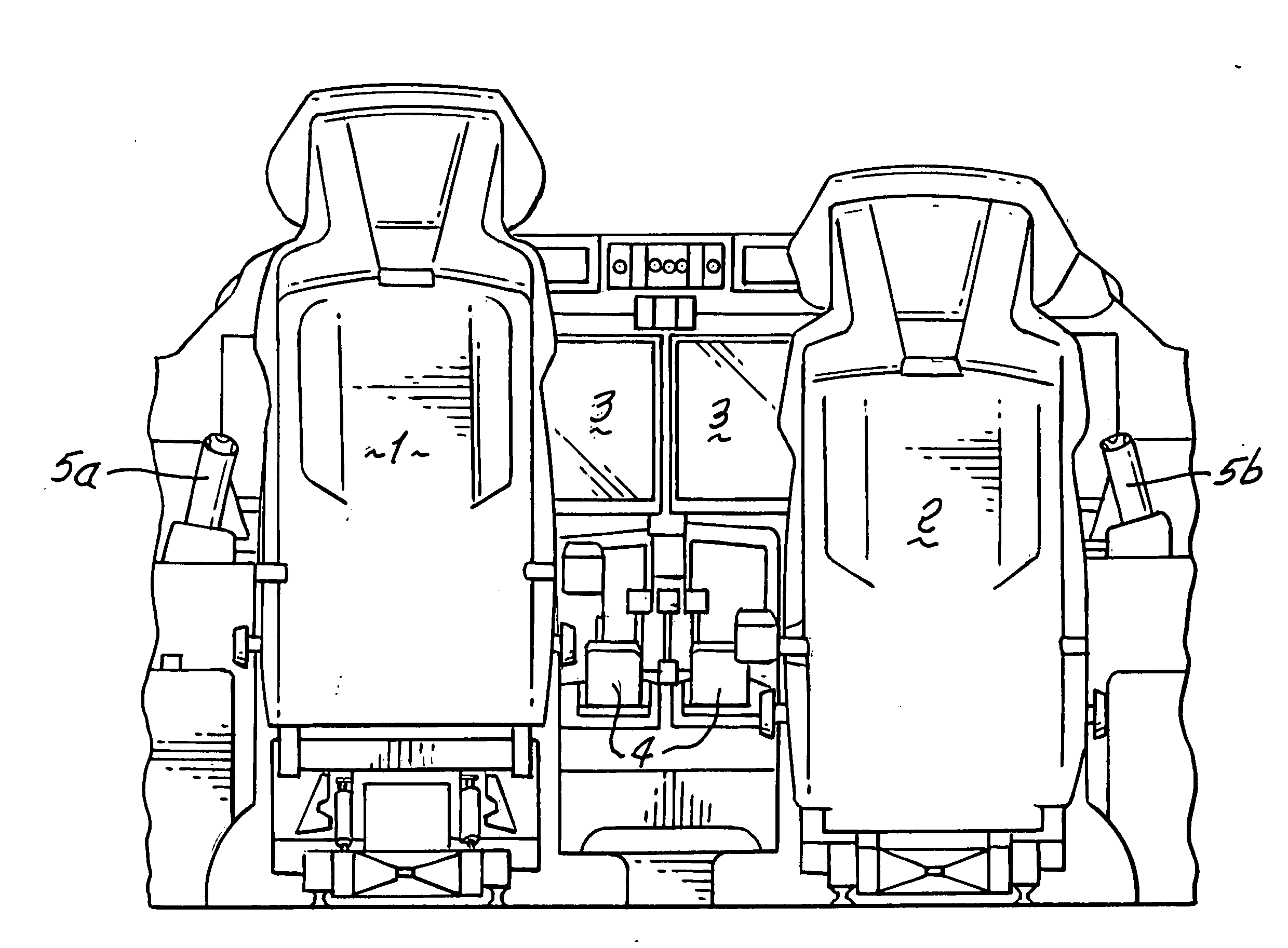
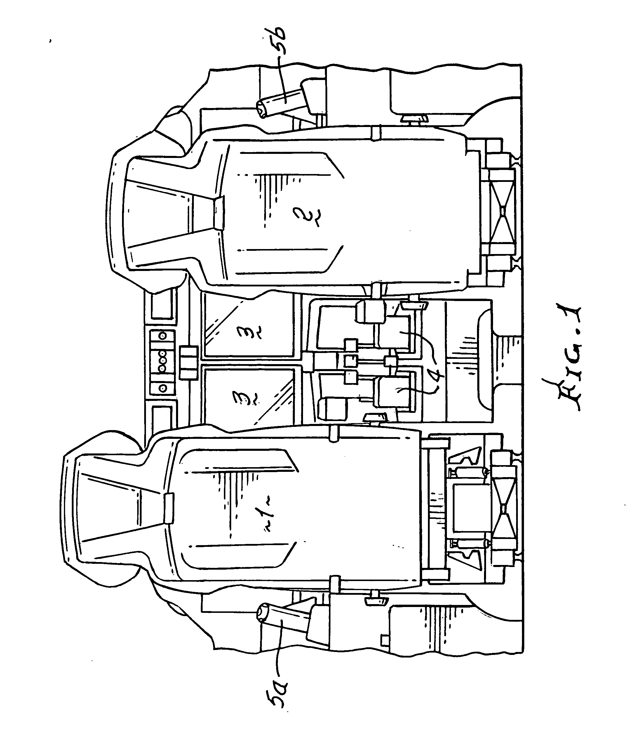
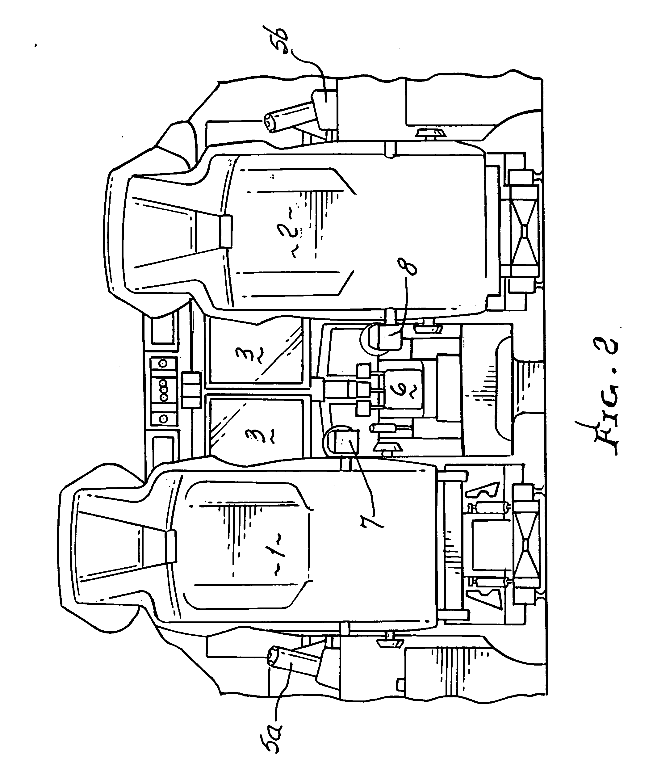
[0020]In FIG. 1 a standard “glass” cockpit is shown with pilot seat 1, copilot seat 2, flat screen displays 3, pedestal-mounted CCDs 4, and primary flight “side-stick” controllers 5a on the pilot's side and 5b on the copilot's side. FIG. 2 shows a modified cockpit arrangement that incorporates the invention. In this embodiment, a single pedestal-mounted CCD is shown 6 which is shared by the pilot and copilot when they do not wish to use the invention. It is also possible to replace all traditional CCDs with the invention. The invention permits a significant reduction in size of the central pedestal which is advantageous for pilot ingress and egress and also for space-limited cockpits. It can also be used to make space available on the pedestal for other avionics permitting improved cockpit layouts. For aircraft with side console-mounted CCDs, the invention can similarly save space by using an outboard seat armrest installation in place of the traditional CCDs. FIG. 2 also shows the ...


PUM


Abstract

The invention concerns an improved CCD integration within pilot seat armrests, with benefits including ease and accuracy of CCD use, premium space savings on cockpit consoles, the ability to be retracted when not in use, always remaining within comfortable and easy reach of tall and short pilots alike and not interfering with other devices such as “side-stick” flight controls. The compactness and accuracy of use of the invention, its ability to be stowed, and its space-saving features set this CCD apart from existing CCDs and improve cockpit structure and pilot operation of aircraft that employ this invention.

Description

BACKGROUND OF THE INVENTION[0001]This invention relates to the design of aircraft cockpit screen cursor control devices. Modern aircraft cockpits, so-called “glass cockpits,” incorporate large, flat-screen digital displays. The data displayed on the screens can be controlled, and interacted with, by pilots using various input methods, used singly or in combination. These include keyboards, touch screens, and devices that are somewhat analogous to desktop computer mice. These mouse-like pointing devices are referred to as cursor control devices.[0002]Due to human factor requirements of having to interact with cockpit avionics while the aircraft is in motion, such as while maneuvering or bouncing while taxiing or while flying through turbulence, typical desktop computer input devices are often inappropriate. Cursor control devices (CCDs) are designed primarily for use in an unsteady environment. Current CCD designs are bulky, and consume premium space either on the center pedestal bet...

Claims


Application Information

Patent Timeline
Patent Type & Authority Applications(United States)
IPC IPC(8): B64C13/04B64D11/06
CPCB64C13/04B64D11/0644B64D11/0689B64C13/042B60N2/797
Inventor MILLER, JEFFREY C.
Owner AERION INTPROP MANAGEMENT CORP
Why Eureka
Try Eureka