Mammography imaging arrangement for tomosynthesis

a mammography and imaging arrangement technology, applied in the field of tomosynthesis process, can solve the problems of affecting the overall time needed for imaging procedures like this, and affecting the recovery of patients, etc., and achieves the effect of simple updating of conventional mammography apparatuses

Active Publication Date: 2017-01-05
PLANMED OY
View PDF9 Cites 10 Cited by
  • Summary
  • Abstract
  • Description
  • Claims
  • Application Information

AI Technical Summary

Benefits of technology

[0015]The object of the present invention and its preferable embodiments is to enable tomosynthesis of individual 2D images taken by a mammography apparatus such that the mutual geometry of the imaging means of the imaging apparatus is determined, separately, for each individual image when taking the image. The object is thus a solution thanks to which the actual imaging device does not necessarily have to be extremely precise of its mechanical structures and movements as the imaging geometry can always be calculated based on calibration information projected into each individual 2D image. Preferable embodiments of the invention include solutions which can enable a relatively simple updating of conventional mammography apparatuses to be applicable also for tomosynthesis imaging.

Problems solved by technology

When breast cancer is detected on the basis of symptoms, the illness has often already developed into a stage where the prognosis for recovery is relatively poor.
As tissue layers lie on top of each other in the direction of the X-ray beam in such imaging, these irradiations produce two-dimensional images in which strongly absorbing structures may hinder the detection of structures lying beneath them.
The overall time needed for an imaging procedure like this tends to become quite long.
It is a challenge when such a mechanical structure is used to be able to come up with a construction which would also be practical in view of using the apparatus for conventional 2D screening mammography.
When certain gaps and tolerances typically relate to mechanical structures, knowledge in theory of the dimensions and paths of the imaging apparatus and its components does not necessarily enable achieving a required precision.
While the comments of the imaging apparatus more during the imaging process they are vulnerable to external forces, such as gravity, and even the patient positioned for imaging may cause when leaning or supporting herself on the imaging apparatus during imaging, bending in the apparatus structures or movement of them diverging from the calculated.
Generally speaking, it is not necessarily that straightforward to modify a mammography apparatus designed for conventional screening to also be applicable for tomosynthesis imaging and, correspondingly, it is not necessarily that straightforward to make a mammography apparatus designed for tomosynthesis imaging also applicable for conventional screening.

Method used


Image

  • Mammography imaging arrangement for tomosynthesis
  • Mammography imaging arrangement for tomosynthesis
  • Mammography imaging arrangement for tomosynthesis

Examples


Embodiment Construction

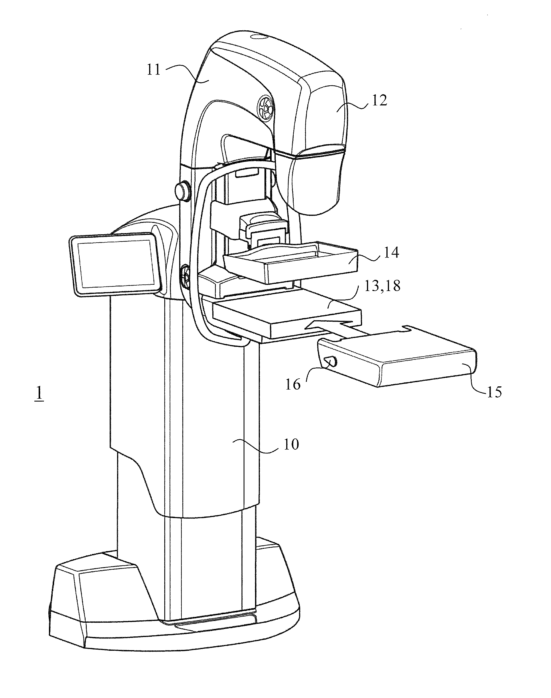
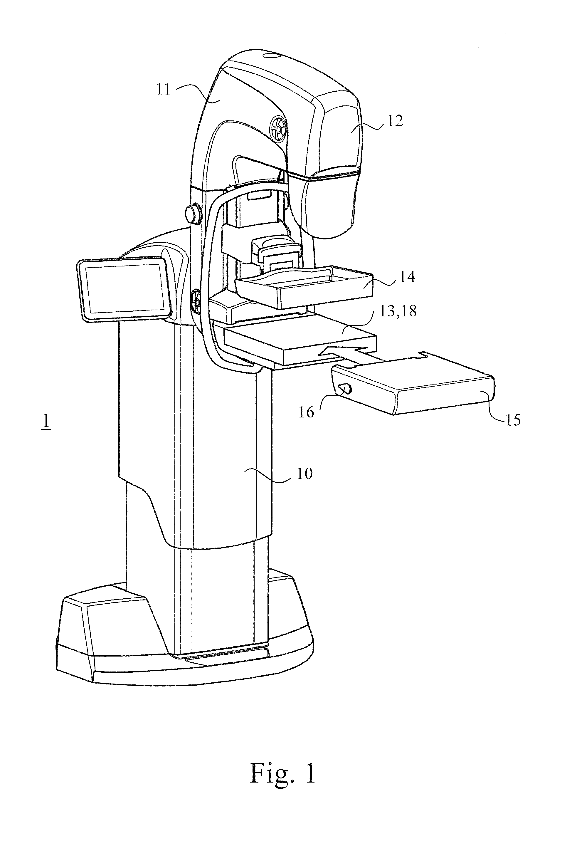
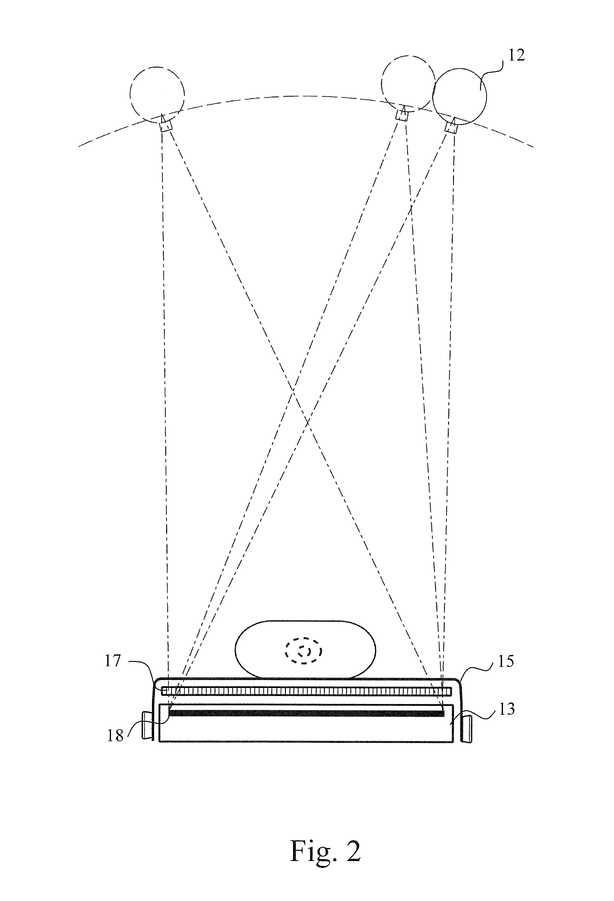
[0027]FIGS. 1-3 show typical constructions of a mammography apparatus. The mammography apparatus (1) of FIG. 1 consists of a frame part (10) and a C-arm (11) (more commonly an arm structure (11)) attached to it. In the top part of the C-arm (11) inside its coven is arranged a source of radiation (12) which is arranged to generate a beam, which passes through an upper compression plate (14) of the mammography apparatus (when such an upper compression plate is attached to the apparatus) and towards a detector (18) positioned in a detector housing (13). The detector housing (13) or a corresponding structure is typically arranged inside a lower tray structure (15), into connection with which lower tray structure (15) can be integrated a grid structure (17) which absorbs radiation scattering from the object being imaged. The lower tray structure (15) can be a fixed structure in the apparatus or it can be arranged detachably connected. As the top surface of the lower tray structure (15) t...


PUM


Abstract

The invention relates to a tomosynthesis process in the context of mammography, in which several individual images of a breast are taken at different projection angles and in which of information thus acquired, tomographic images are synthesized with the help of an applicable image processing software. The mutual geometry of the imaging means of the imaging apparatus when taking these individual images is determined according to the invention by arranging in the imaging apparatus a calibration structure (20), which includes balls (21) or other small objects absorbing X-radiation which are such placed that their projections will become imaged on said individual images.

Description

FIELD OF INVENTION[0001]The present invention relates to a tomosynthesis process in the context of mammography, in which process several images of a breast are taken at different projection angles, such as in the range of ±15 degrees from the vertical, and in which one can synthesize tomographic images from the image information thus acquired with the help of applicable image processing software.DESCRIPTION OF PRIOR ART[0002]Breast cancer is the most common type of cancer in women. According to studies, about one in every ten women contracts breast cancer at some point in their lives. When breast cancer is detected on the basis of symptoms, the illness has often already developed into a stage where the prognosis for recovery is relatively poor. Some of the cases are detected in screening programs arranged in many countries for women over the age of 40. Screening often reveals a cancer at a very early stage, whereby its treatment can be started in time and recovery is thus more likel...

Claims


Application Information

Patent Timeline
Patent Type & Authority Applications(United States)
IPC IPC(8): A61B6/00A61B6/02
CPCA61B6/583A61B6/502A61B6/4464A61B6/4452A61B6/025A61B6/5258A61B6/582
Inventor ASPELUND, LEOLAUKKANEN, TAPIONYHOLM, KUSTAALAHELMA, JAAKKO
Owner PLANMED OY
Why Eureka
Try Eureka