Supercharge Your Innovation With Domain-Expert AI Agents!

A belt tensioner for a belt drive

a belt drive and tensioner technology, applied in the direction of belt/chain/gearing, mechanical equipment, gearing, etc., can solve the problems of hydraulic tensioner being more complex and expensive than conventional mechanical tensioner, and the life of the tensioner is limited

Active Publication Date: 2017-01-05
DAYCO EURO
View PDF24 Cites 3 Cited by
  • Summary
  • Abstract
  • Description
  • Claims
  • Application Information

AI Technical Summary

Benefits of technology

The technical effect of the present invention is to provide a mechanical tensioner that solves the problems of the prior art.

Problems solved by technology

These bushings are subject to wear; in consequence, the tensioner has a limited life, in any case shorter than that of the vehicle.
However, hydraulic tensioners are more complex and expensive than conventional mechanical tensioners.

Method used


Image

  • A belt tensioner for a belt drive
  • A belt tensioner for a belt drive
  • A belt tensioner for a belt drive

Examples


Embodiment Construction

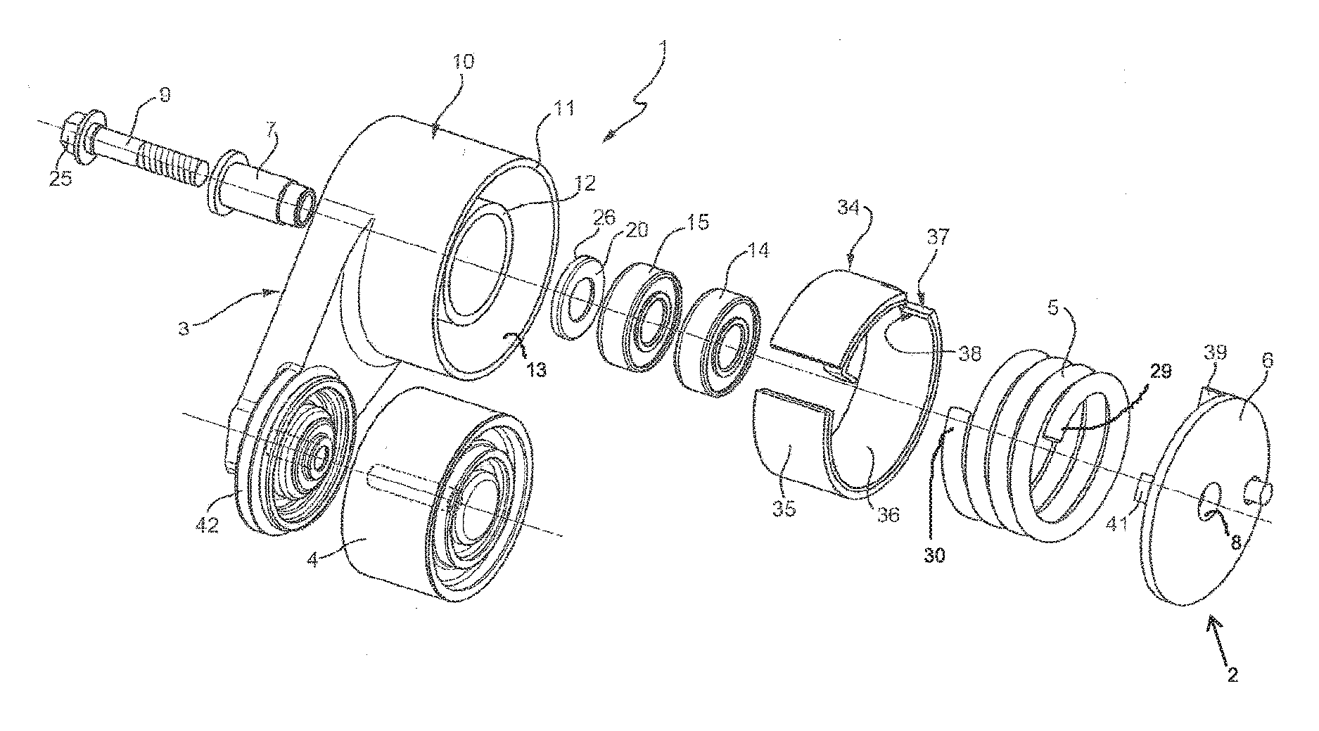
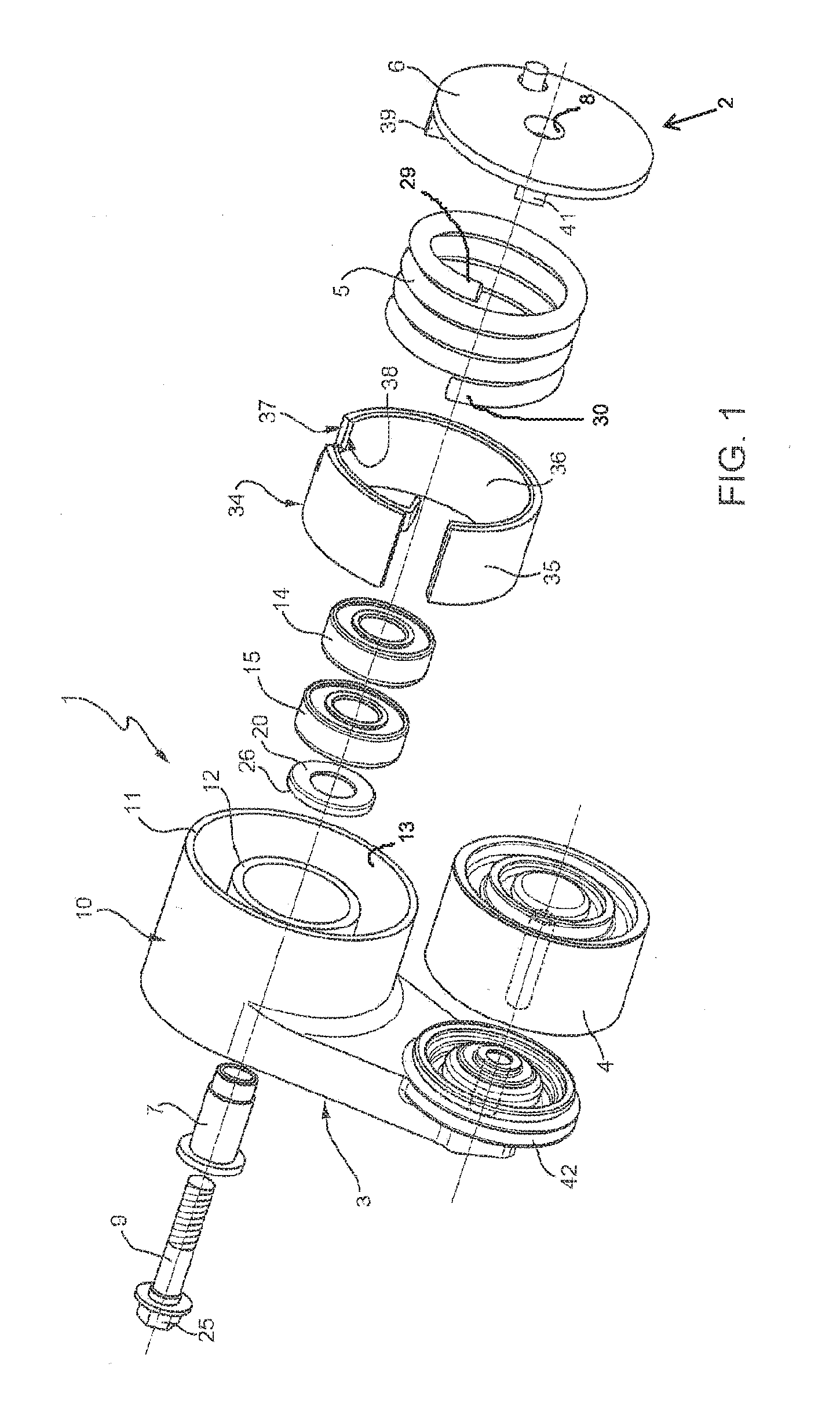
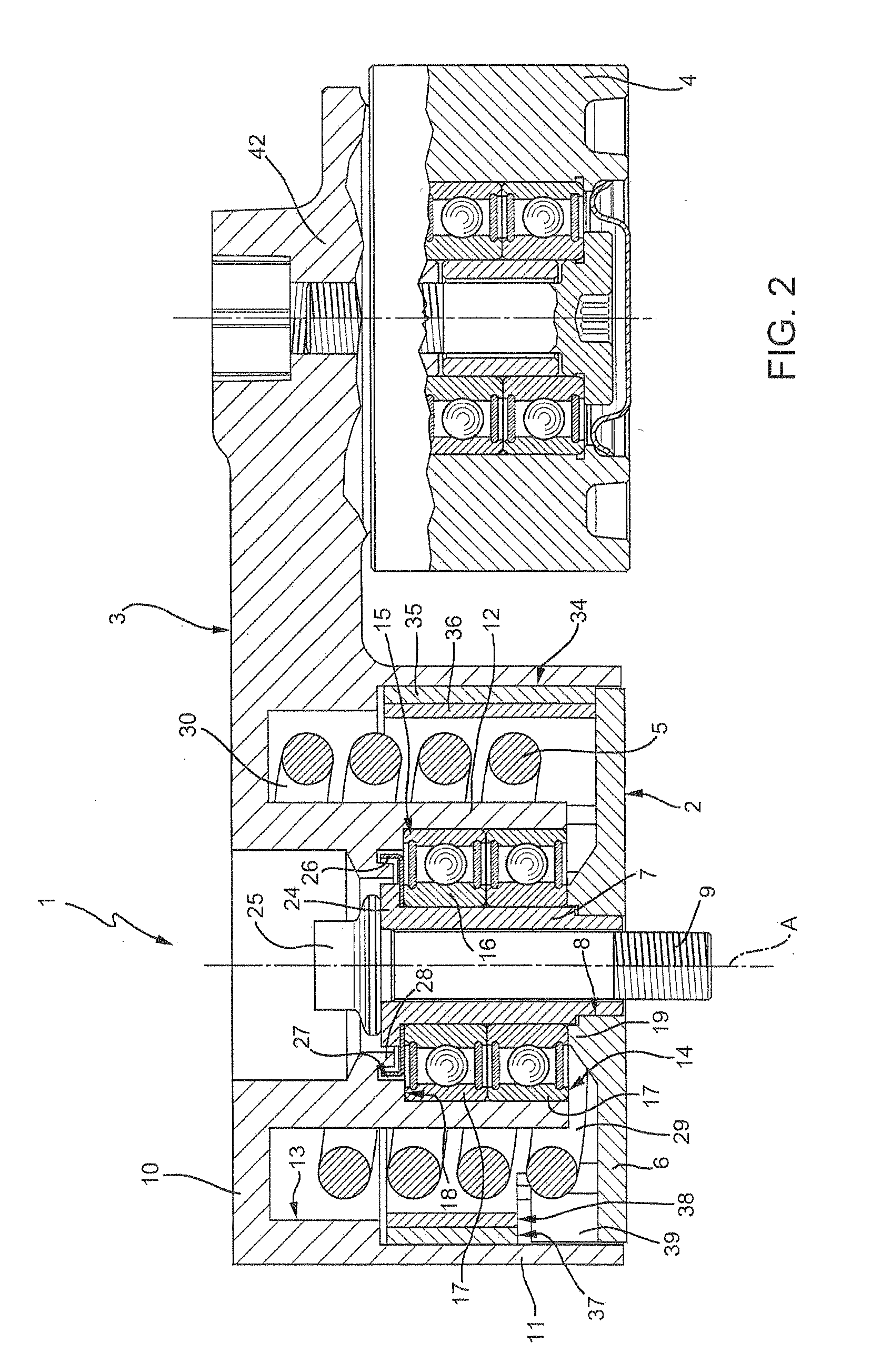
[0017]With reference to the figures, a tensioner for an accessory drive of an industrial vehicle in indicated, as a whole, by reference numeral 1.

[0018]The tensioner basically comprises a fixed part 2 suitable for being fastened to the engine, an arm 3 that is rotatable with respect to the fixed part 2 about an axis A, a pulley 4 rotatably carried by the arm 3 and suitable for cooperating with a belt (not shown) and a spring 5 constrained to the fixed part 2 and to the arm 3 to exert an elastic load on the latter such as to push the pulley 4 into contact with the belt.

[0019]More specifically, the fixed part 2 comprises a base plate 6 suitable for resting on a surface of the engine and a hollow, substantially cylindrical pivot 7, aligned along axis A, embedded in a central hole 8 of the base plate 6 and projecting from the latter.

[0020]The fixed part 2 can be fastened to the engine by a screw 9 that passes through the pivot 7.

[0021]The arm 3 includes a hollow, substantially cylindric...


PUM


Abstract

A belt tensioner for a belt drive of a motor vehicle engine, comprising: a fixed part configured to be fixed with respect to the engine and provided with a pivot defining a rotation axis; an arm having a connection portion hinged to the pivot and rotatable about the rotation axis and an opposite portion rotatably supporting a pulley configured to cooperate with a belt of the drive; a main spring interposed between the fixed part and the arm to exert thrust on the arm such as to rotate said arm towards the belt; and at least one rolling bearing interposed between the arm and the pivot to support the arm and ensure the alignment thereof.

Description

TECHNICAL FIELD[0001]The present invention relates to a belt tensioner for a belt drive, and particularly, but not exclusively, for an accessory drive of an industrial vehicle.BACKGROUND ART[0002]As is known, tensioners for accessory drives comprise a fixed part configured to be fastened to the engine and defining a rotational pivot, an arm rotatably supported on the rotational pivot and carrying, at one end, a pulley suitable for cooperating with a drive belt and a spring acting on the arm to tension the belt.[0003]Known tensioners of the above-stated type must meet certain functional requirements aimed at optimizing the life of the tensioner and of the belt. In particular, it is necessary that the arm is kept in perfect alignment, i.e. it rotates on a plane orthogonal to the axis of the pivot and is not subjected to oscillations outside the plane that might result in noise, premature wear and, eventually, belt slippage.[0004]The alignment function is normally delegated to one or m...

Claims


Application Information

Patent Timeline
IPC IPC(8): F16H7/12F16H7/08
CPCF16H7/1218F16H2007/081F16H2007/084F16H2007/0865F16H7/0829F16H7/1209F16H2007/0893
Inventor CARICCIA, GIANLUCACIMINO, ANTONINO
Owner DAYCO EURO
Features
  • R&D
  • Intellectual Property
  • Life Sciences
  • Materials
  • Tech Scout
  • Unparalleled Data Quality
  • Higher Quality Content
  • 60% Fewer Hallucinations
Learn More