Optical imaging lens with a fixing structure

Active Publication Date: 2017-01-05
GENIUS ELECTRONICS OPTICAL XIAMEN
View PDF1 Cites 3 Cited by
  • Summary
  • Abstract
  • Description
  • Claims
  • Application Information

AI Technical Summary

Benefits of technology

[0006]The invention is directed to an optical imaging lens with a fixing

Problems solved by technology

Consequently, a risk of negative impact on image quality due to lens dis

Method used


Image

  • Optical imaging lens with a fixing structure
  • Optical imaging lens with a fixing structure
  • Optical imaging lens with a fixing structure

Examples


Embodiment Construction

[0023]Before the invention is described in detail, it should be noted that the same elements are indicated by the same reference numbers in the following paragraphs.

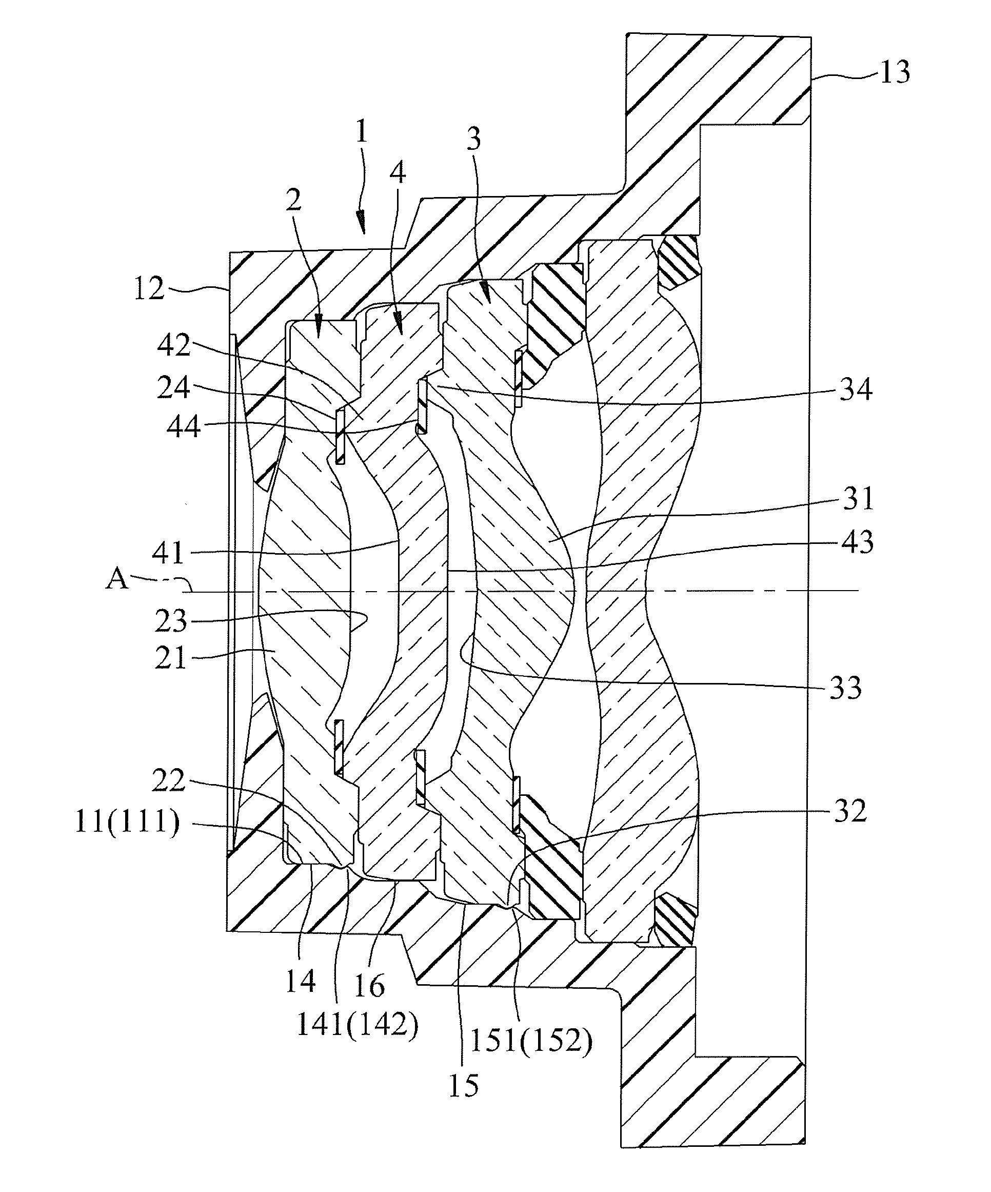
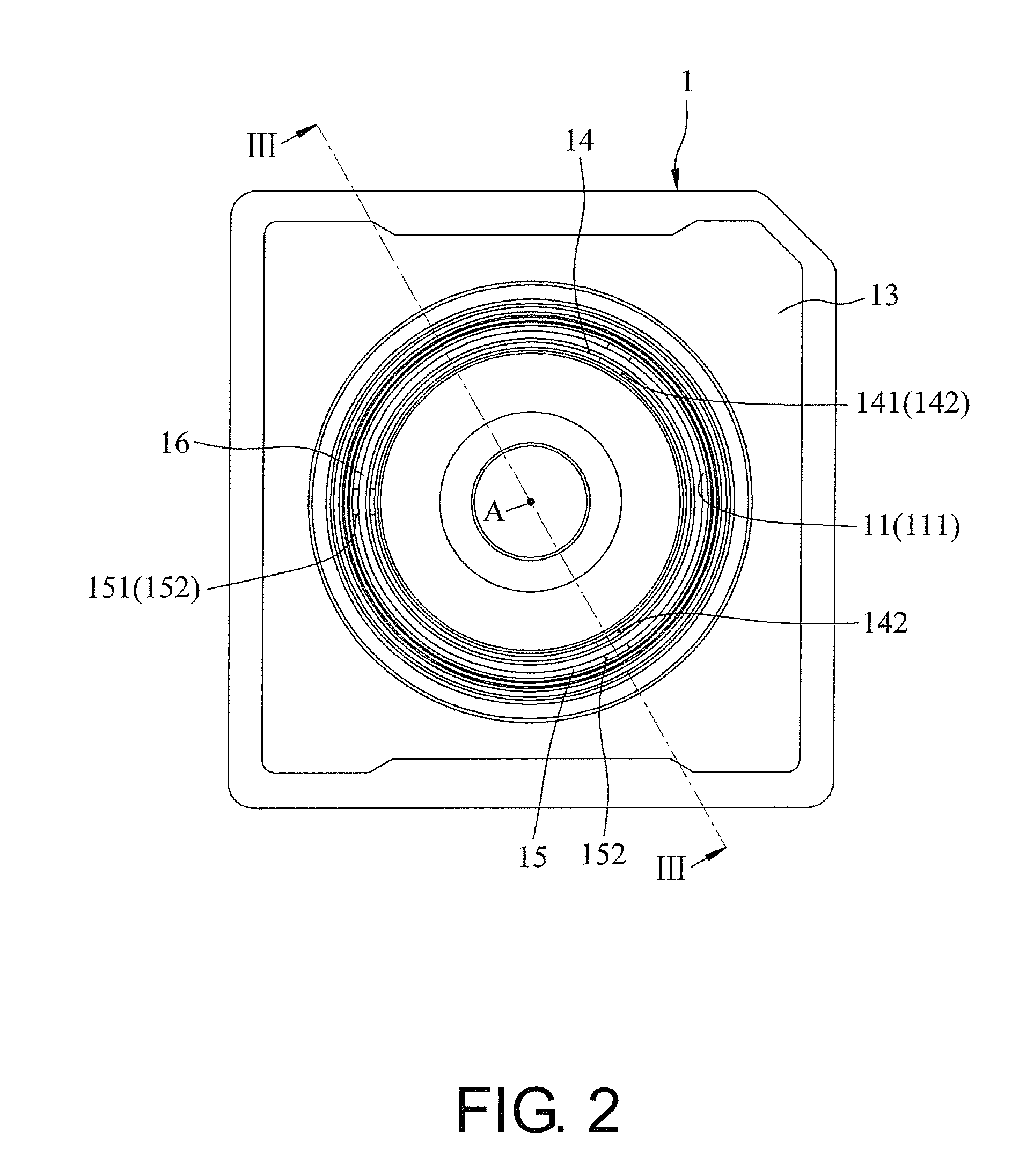
[0024]Referring to FIG. 2 to FIG. 5, a first exemplary embodiment of an optical imaging lens with a fixing structure of the invention includes a barrel 1, a first optical element 2, a second optical element 3 and a third optical element 4. One of the barrel 1 and the first optical element 2 has deformable elasticity. One of the barrel 1 and the second optical element 3 has the deformable elasticity.

[0025]The barrel 1 includes an inner circumferential surface 11 surrounding an axis A and defining an accommodation space 111, an object side 12 and an image side 13 spaced at two ends of the axis A and interconnecting with the accommodation space 111, a first mounting portion 14 integrally formed around the inner circumferential surface 11, a second mounting portion 15 arranged in line with the first mounting portion 14 along...


PUM


Abstract

A lens includes a barrel and a first optical element. The barrel includes an inner circumferential surface surrounding an axis and defining an accommodation space, an object side and an image side spaced at two ends of the axis and interconnecting with the accommodation space, and a first mounting portion integrally formed around the inner circumferential surface. The first mounting portion includes a first blocking portion having a first blocking surface corresponding to the object side. The first optical element is received in the accommodation space, and disposed in the first mounting portion, and includes a first body portion and a first stopping portion. The first stopping portion includes a first stopping surface leaning against the first blocking surface. The distance between an outermost edge of the first stopping portion and the axis is greater than the distance between an innermost edge of the first blocking portion and the axis.

Description

CROSS-REFERENCE TO RELATED APPLICATION[0001]This application claims the priority benefit of Chinese application serial no. 201510386904.7, filed on Jul. 3, 2015. The entirety of the above-mentioned patent application is hereby incorporated by reference herein and made a part of this specification.BACKGROUND OF THE INVENTION[0002]Field of the Invention[0003]The invention relates to an optical lens, and particularly relates to an optical imaging lens with a fixing structure.[0004]Description of Related Art[0005]Referring to FIG. 1, a conventional optical lens includes a barrel 5 including an inner circumferential surface 51 surrounding an axis B and defining an accommodation space 511, and a plurality of optical lenses 6 installed in the accommodation space 511. The optical lenses 6 and the barrel 5 are mounted and fixed by adopting a dispensing curing method. However, when the optical lens is subjected to an impact of an external force, if only depend on a retention force of the adhe...

Claims


Application Information

Patent Timeline
IPC IPC(8): G02B7/02G02B9/34
CPCG02B7/022G02B13/004G02B5/005G02B7/021
Inventor FU, WEI-WEICHEN, ZHEN-MULI, WEI-MINZHAN, HAI-BINCHO, HUNG-CHANG
Owner GENIUS ELECTRONICS OPTICAL XIAMEN
Why Eureka
Try Eureka