Insect capturing device

Active Publication Date: 2017-01-12
KILLGERM GROUP
View PDF4 Cites 16 Cited by
  • Summary
  • Abstract
  • Description
  • Claims
  • Application Information

AI Technical Summary

Benefits of technology

[0017]In one embodiment, a reflector can be included for directing light emitted by the LEDs onto the reflection surface. In this way, the amount of stray light falling upon a glue board that may be received in the insect disabling portion can be reduced. Light falling on the glue board can otherwise lead to drying of the glue, reducing the effectiveness of the board in capturing insects that land upon it. The reflector can also act to concentrate the light produced by the LEDs onto the reflection surface, thereby maximising the light reflected out from the housing. The reflector can further act to prevent stray light emitted by the LEDs from leaving the housing of the device directly, which can otherwise lead to eye or skin damage in a person exposed to the insect capturing device. The reflector can, for example, be a reflector cone such as a parabolic reflector cone.
[0018]In one embodiment, a barrier can be positioned between the insect disabling portion and the reflection surface, again for reducing the amount of light emitted by the LEDs that falls on a glue board that may be received in the insect disabling portion.
[0019]In one embodiment, more than two reflection surfaces can be provided. The insect disabling portion can be loca

Problems solved by technology

Fluorescent tubes also use mercury and their construction and subsequent disposal is not considered to be environmentally friendly.
Although it may be desirable to use L

Method used


Image

  • Insect capturing device
  • Insect capturing device
  • Insect capturing device

Examples


Embodiment Construction

[0031]Embodiments of the present invention are described in the following with reference to the accompanying drawings.

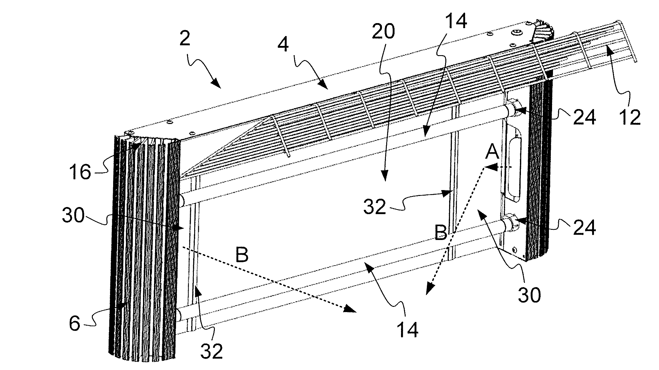
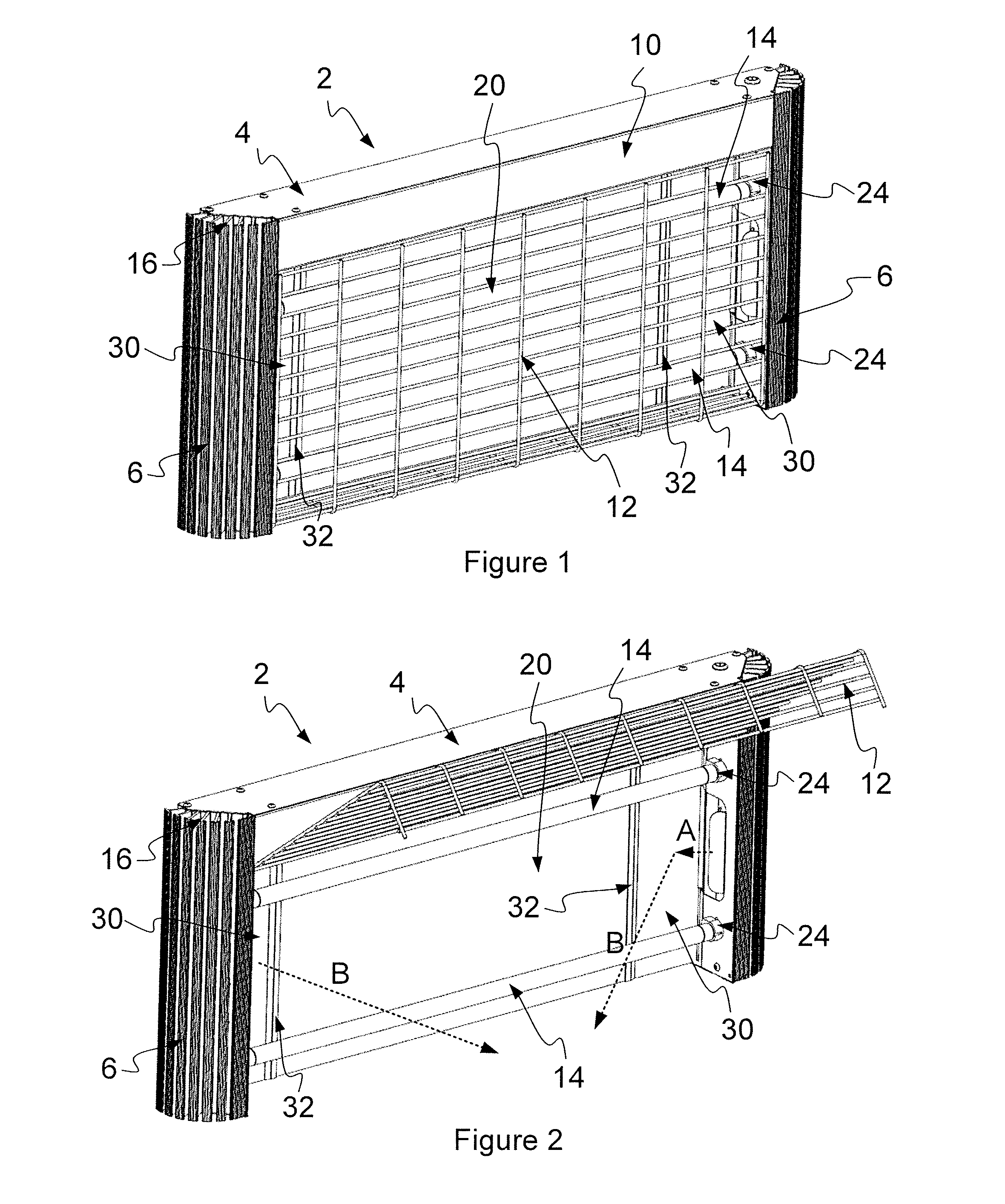
[0032]FIG. 1 illustrates an insect capturing device 2 in accordance with an embodiment of the invention. The insect capturing device includes a housing 10. The housing 10 forms an enclosure that contains various components of the device 2 such as one or more light emitting diodes 40 and an insect disabling portion 20 as will be described in greater detail below. The housing 10 in this example includes a top section 4, a grille 12 which is provided at the front of the housing 10, a back section 8 (see FIGS. 4-7) and two side portions, which in this embodiment are provided in the form of heat sinks 6 including a plurality of heat sink fins 16. The features of the housing 10 of the insect capturing device can be constructed using any suitable material. In the present example, metals such as aluminium or stainless steel have been used.

[0033]In FIG. 1, the grille 12 is sh...


PUM


Abstract

An insect capturing device and a method of using the same. The insect capturing device includes a housing. The insect capturing device also includes an insect disabling portion. The insect capturing device also includes one or more light emitting diodes (LEDs) operable to emit light for attracting insects. The insect capturing device further includes a reflection surface. The LEDs are oriented to direct light onto the reflection surface for reflecting the light out from the housing to attract insects onto the in sect disabling portion.

Description

FIELD OF THE INVENTION[0001]This invention relates to an insect capturing device.BACKGROUND OF THE INVENTION[0002]Known insect capturing devices typically use UV light having a wavelength approximately in the range 300 nm ≧λ≧400 nm to attract insects onto an insect disabling portion such as a glue board or a high voltage killing grid provided within a housing. The UV light is produced using a fluorescent tube.[0003]For example, WO 2012 / 104598 A1 describes an insect catching device which comprises a housing. A radiation source which attracts insects is mounted inside the housing and an insect catching member is located within the housing. The insect catching member has a catching surface on which an amount of an adhesive material is provided. The front portion of the housing defines an aperture which allows insects to enter the housing and be caught on the adhesive material. The housing defines a vent located separately from the aperture and positioned to create an airflow into the h...

Claims


Application Information

Patent Timeline
IPC IPC(8): A01M1/04A01M1/14A01M1/22
CPCA01M1/04A01M1/145A01M1/223
Inventor MCGOWAN, NEILLEIGH, ZAPHOD
Owner KILLGERM GROUP
Why Eureka
Try Eureka