
Interactive network monitoring and analysis

a network monitoring and network traffic technology, applied in the field of network management, can solve the problems of reducing the effectiveness of tools for on-line or real-time analysis, and achieve the effect of facilitating real-time data capture control and analysis

Inactive Publication Date: 2007-06-21
OPNET TECH LLC
View PDF12 Cites 87 Cited by
  • Summary
  • Abstract
  • Description
  • Claims
  • Application Information

AI Technical Summary

Benefits of technology

[0006] Although the available tools are effective for recording information related to each monitored message, the sheer volume of messages over a monitored channel reduces the tool's effectiveness for on-line, or real-time, analysis. U.S. patent applications 2004 / 0093413, 2004 / 0098611, and 2004 / 0133733 filed 13 May 2004, 20 May 2004, and 8 Jul. 2004 for Bean et al. and incorporated by reference herein, disclose techniques for organizing captured network data to facilitate an interactive display of the volume of data communicated through a router over time. Summary information, in the form of histogram data, is stored for each defined time period, with pointers to the detailed message data corresponding to this histogram data. The user is provided options to pan and zoom through this volume data, including the ability to view multiple time lines at different time scales. Because this data is summarized as histogram data, these panning and zooming actions can be performed quickly.
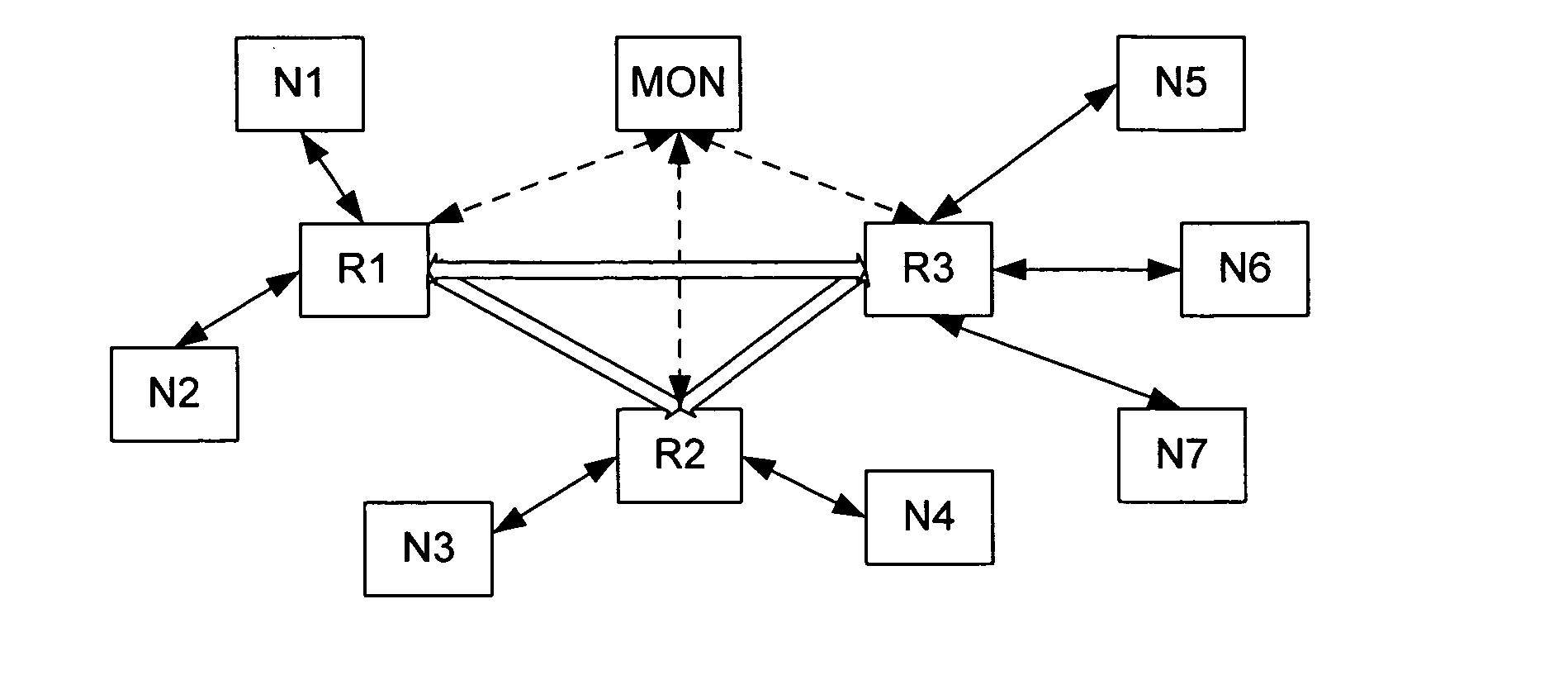
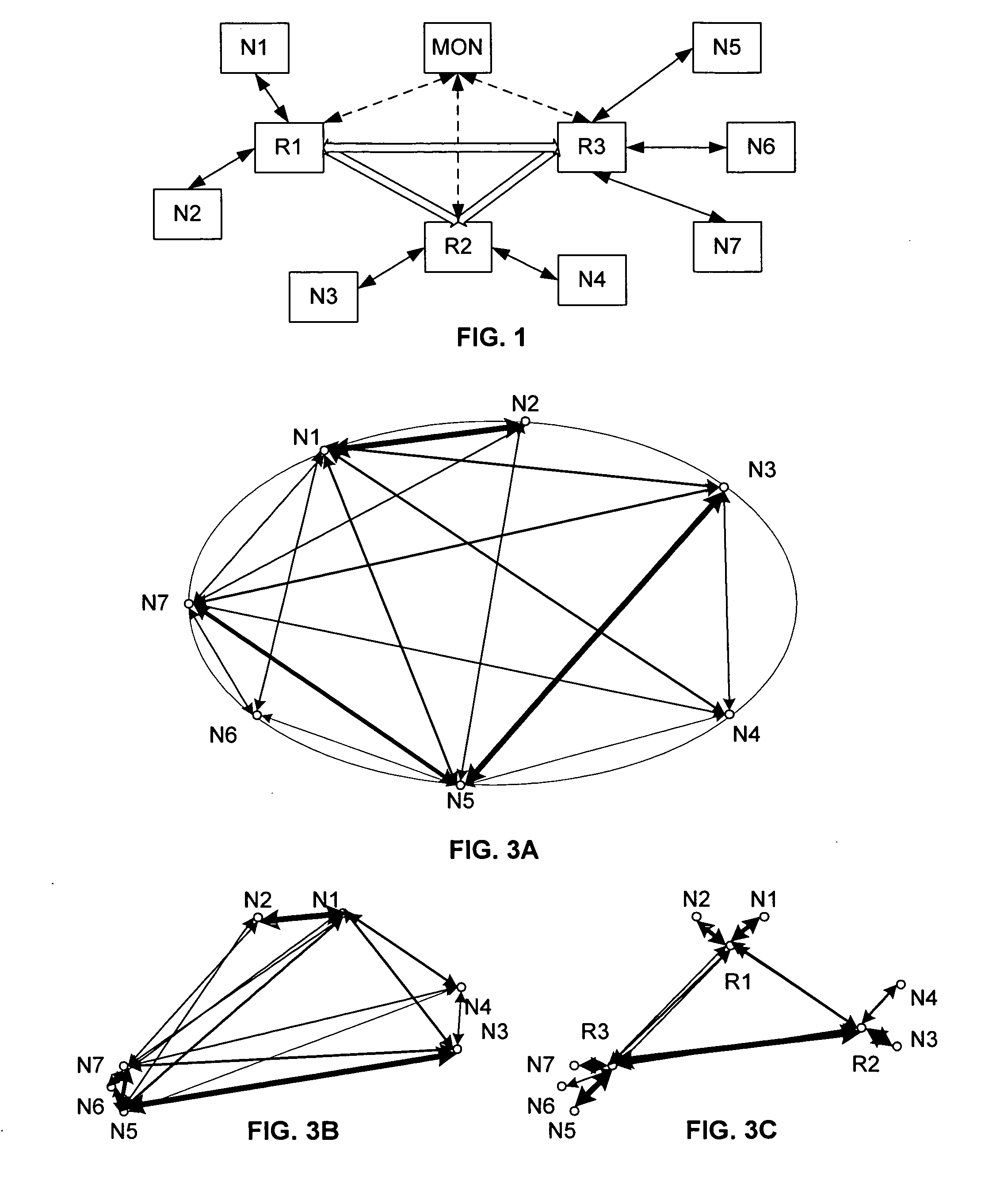
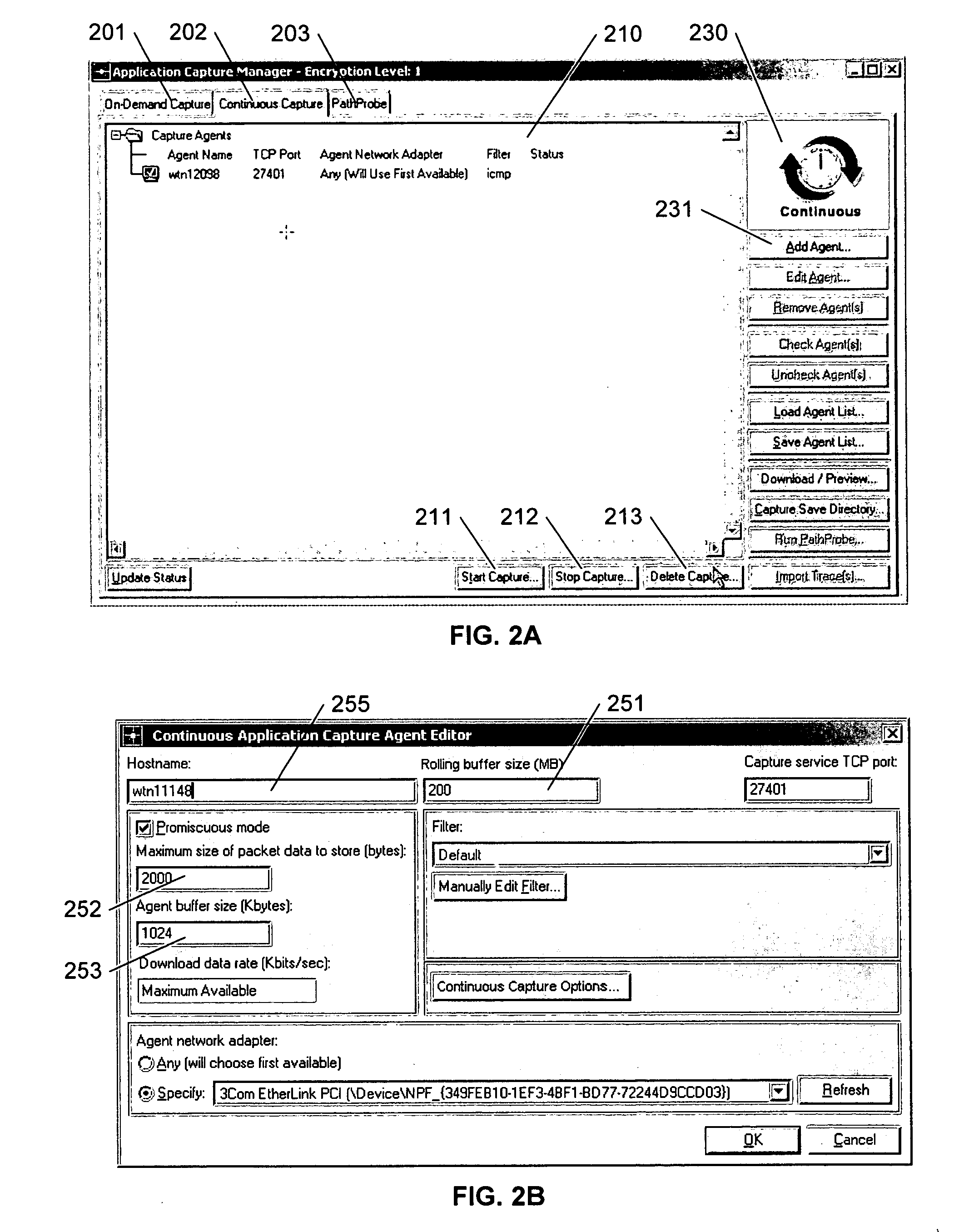
[0008] It would be advantageous to organize captured message traffic by categories, to facilitate real-time data-capture control and analysis based on such categorization. It would be advantageous if such categorization distinguished among the sources and / or destinations of the messages. It would also be advantageous if a user were able to customize and control the data capture tools while performing this network traffic analysis.

Problems solved by technology

Although the available tools are effective for recording information related to each monitored message, the sheer volume of messages over a monitored channel reduces the tool's effectiveness for on-line, or real-time, analysis.
Although the display of the volume of data flowing through a router over time can facilitate an analysis of traffic flow, it does not, per se, facilitate the analysis of traffic patterns, and additional analysis of the underlying detailed data is required to identify the causes of the traffic.

Method used


Image

  • Interactive network monitoring and analysis
  • Interactive network monitoring and analysis
  • Interactive network monitoring and analysis

Examples


Embodiment Construction

[0018] In the following description, for purposes of explanation rather than limitation, specific details are set forth such as the particular architecture, interfaces, techniques, etc., in order to provide a thorough understanding of the concepts of the invention. However, it will be apparent to those skilled in the art that the present invention may be practiced in other embodiments, which depart from these specific details. In like manner, the text of this description is directed to the example embodiments as illustrated in the Figures, and is not intended to limit the claimed invention beyond the limits expressly included in the claims. For purposes of simplicity and clarity, detailed descriptions of well-known devices, circuits, and methods are omitted so as not to obscure the description of the present invention with unnecessary detail.

[0019] The invention is presented herein using the generic term of ‘message’ to identify a communication from a source node of a network to on...


PUM


Abstract

A network monitoring system and method processes captured message data to create a plurality of categories, provides summary data corresponding to each category, and displays the categorized summary data. The categories preferably include an identification of the source node and destination node of each message, and the summary data includes the amount of traffic communicated between each pair of nodes. The display of this summary data includes a graphic display that provides a visual indication of each pair and the volume of traffic between the nodes of the pair.

Description

[0001] This application claims the benefit of U.S. Provisional Patent Application 60 / 750,667, filed 15 Dec. 2005 and U.S. Provisional Patent Application 60 / 773,563, filed 15 Feb. 2006.BACKGROUND AND SUMMARY OF THE INVENTION [0002] This invention relates to the field of network management, and in particular to an interactive system and method for capturing and analyzing network traffic. [0003] The complexities of network managing continue to increase, along with the corresponding need for efficient and effective network monitoring to detect and troubleshoot problems, or potential problems. [0004] A variety of tools are available for capturing network traffic, including, for example, discrete hardware devices termed ‘network sniffers’ that monitor traffic on selected channels, and software modules that are embedded within routers or other network switching systems. Generally, these tools are configured to record a portion of the contents of each message that is communicated over the c...

Claims


Application Information

Patent Timeline
IPC IPC(8): H04L12/26
CPCH04L43/026H04L43/028H04L43/045H04L43/062
Inventor MALLOY, PATRICK J.COHEN, ALAINGEHL, RYANSTROHM, JOHN WILSONELSNER, RUSSELL MARK
Owner OPNET TECH LLC
Learn More