Mobile Operations Chassis with Controlled Magnetic Attraction to Ferrous Surfaces

a technology of magnetic attraction and ferrous surfaces, applied in the field of apparatus, to achieve the effect of reducing friction between belts

Inactive Publication Date: 2014-08-21
SEAROBOTICS CORP
View PDF8 Cites 82 Cited by
  • Summary
  • Abstract
  • Description
  • Claims
  • Application Information

AI Technical Summary

Benefits of technology

[0026]Advantageously, a belt engages with two or more wheels or sheaves to provide a traction or bulldozer track type of drive that moves the vehicle or carriage. In this embodiment, the belt is preferably thin and the magnet is mounted behind the belt. Magnets can be provided in association with each wheel or between the wheels and arranged behind the thin belt. Depending on magnet strength and location the belt can be arranged to be compressed against the ferrous surface by magnetic force in those areas where the magnet is located. To minimize friction between the belt and the magnet or magnet supporting structure, one or more rollers can be integrated into the mechanism to maintain a minimal but nonzero separation between the belt and magnet, in which case the separation and the belt contribute to the so-called gap (including air, water and any non-magnetic materials between the magnet and the surface. The magnet presses the traction or track drive against the ferrous surface. The belt engages the ferrous surface with the attachment force running thought the belt, any rollers, the mounting frame of the magnet and ending at the magnet. Magnetic force can be varied by mechanically varying the distance between magnet and attracting surface, for example by angularly positioning magnets or paired sets of magnets as described above. This can be accomplished with a linkage mechanism that is actuated manually, electrically via a motor or solenoid, pneumatically or hydraulically with a linear or rotary actuator.

Problems solved by technology

The surface to be processed may be steeply inclined, vertical, horizontal-inverted or inclined on an underside, presenting additional challenge.
On such surfaces, gravity may not only fail to resist the force of applying tools to the surface, but even worse, gravity may tend to detach the vehicle from the surface regardless of tool force or may urge the vehicle along the surface when displacement is not desired.

Method used


Image

  • Mobile Operations Chassis with Controlled Magnetic Attraction to Ferrous Surfaces
  • Mobile Operations Chassis with Controlled Magnetic Attraction to Ferrous Surfaces
  • Mobile Operations Chassis with Controlled Magnetic Attraction to Ferrous Surfaces

Examples


Embodiment Construction

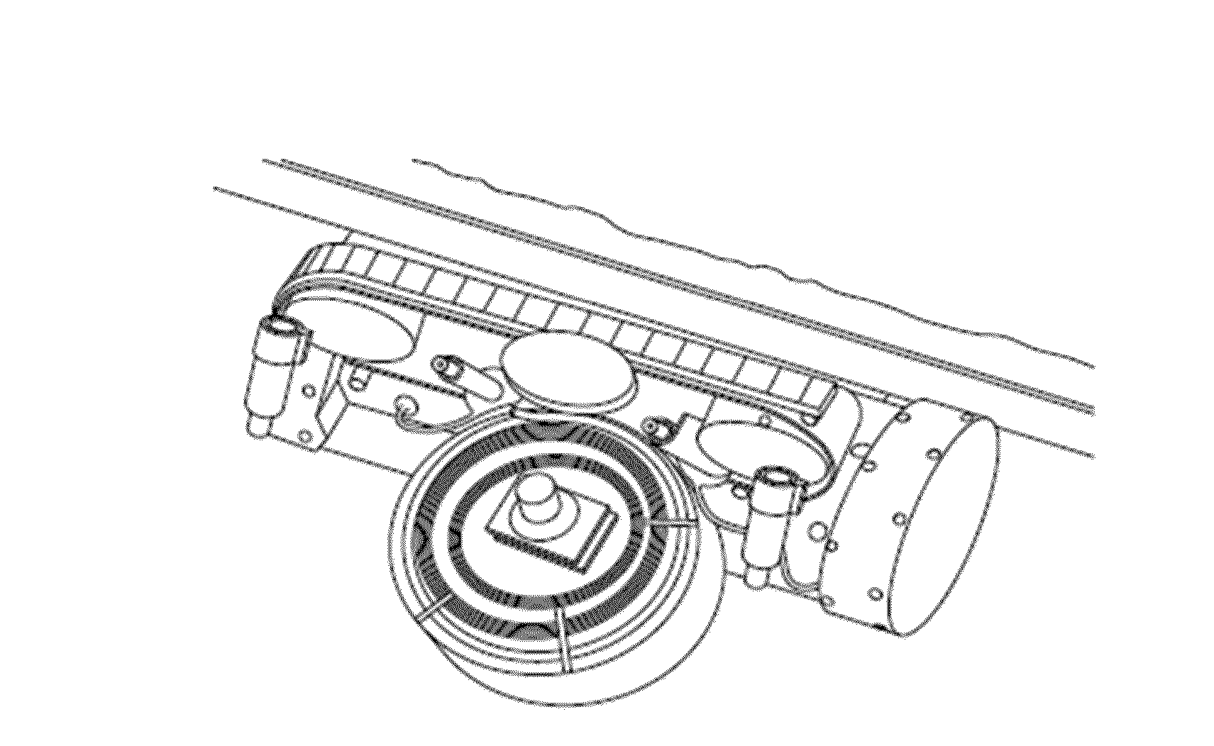
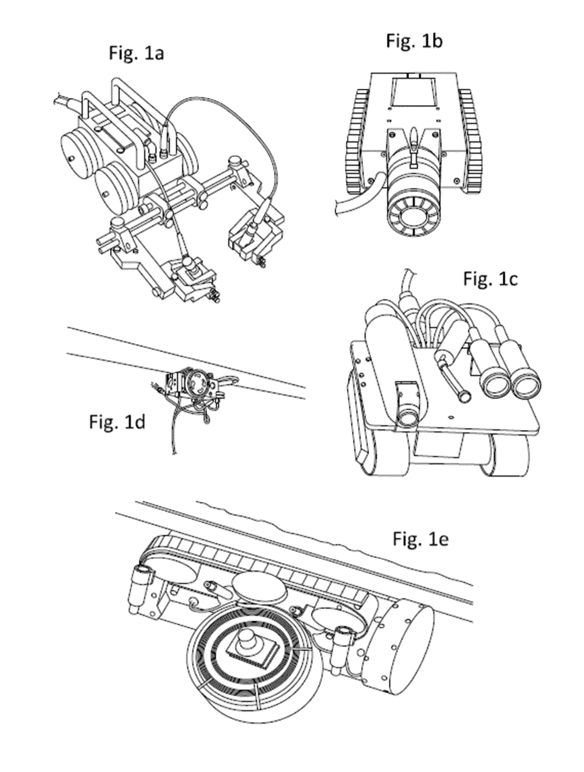
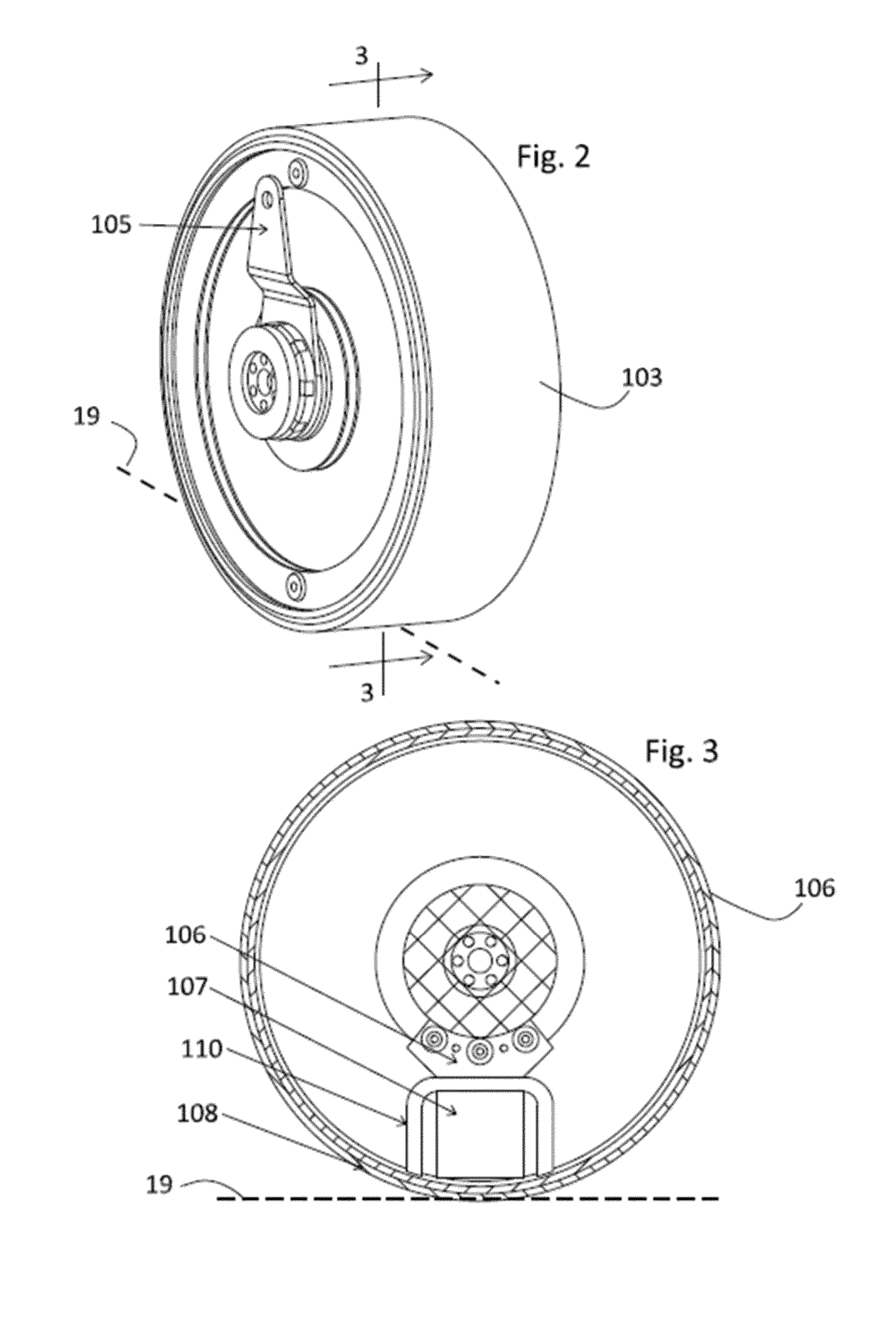
[0061]A structure with controlled magnetic attraction to ferrous surfaces as disclosed herein is advantageously applied to vehicles arranged to maneuver over surfaces such as steel ship hulls, tank walls, bridges, bulwarks and similar ferrous structures in order to inspect and to apply tools to such surfaces. Exemplary embodiments include underwater semi-autonomous vehicles for inspecting ship hull surfaces using cameras and sensors, for applying tools such as brushes and scrapers for de-fouling, etc. In certain embodiments, the vehicles are equipped with magnetic attraction aspects for clinging to ferrous structures during operation and while traversing surfaces. According to other aspects, the vehicles carry particular tools and serve particular functions enabling programmed operations such as assessment of fouling, fouling rates and scheduling to control fouling.

[0062]Cleaning, inspection and tool bearing vehicles or mechanisms are advantageously configured to climb steel surface...


PUM


Abstract

A chassis clings to a ship hull or other ferrous surface by a magnet that moves toward or away from the surface to adjust the magnet air gap and thus the attractive force. The magnet(s) can be the only clinging force or used with other sources such as a suction chamber or fluid jet drive. An internal magnet on a crank mechanism can pivot around a wheel rotation axis inside a wheel body having a non-ferrous traction surface or tire. The magnet gap is least at an angle perpendicular to the surface on which the wheel rests, and larger at an angle oblique to that, for varying the attractive force to two or more levels. The vehicle can be an autonomous hull maintenance device with sensors, controllers and actuators to sense, measure and clean away fouling.

Description

CROSS-REFERENCE TO RELATED APPLICATIONS[0001]This application is a Continuation in Part of pending application Ser. No. 13 / 950,700, filed Jul. 25, 2013, and also claims the benefit of pending U.S. Provisional Patent Application Ser. No. 61 / 773,941, filed Mar. 7, 2013. application Ser. No. 13 / 950,700 is a division of application Ser. No. 12 / 952,973, filed Nov. 23, 2010, now U.S. Pat. No. 8,506,719, and claims the benefit of U.S. Provisional Patent Application No. 61 / 263,680, filed on Nov. 23, 2009. The foregoing applications in their entireties are each hereby incorporated by reference into the present disclosure.BACKGROUND OF THE INVENTION[0002]The invention concerns the field of apparatus that exert force relative to a supporting structure, for example to cling to the structure against the force of gravity or while applying a tool or a fluid jet or other force against the structure, or to provide traction for wheels or tracks that enable the apparatus to move along a surface of the...

Claims


Application Information

Patent Timeline
Patent Type & Authority Applications(United States)
IPC IPC(8): B63B59/08B62D63/04
CPCB62D63/04B63B59/08B08B1/008B08B17/00B60B19/006B63B59/10G05D1/0227G05D1/0231G05D1/0248G05D1/0253G05D1/0255B60Y2200/42B63B2231/30B08B1/00G05D2201/0203A46B13/008A46B2200/30
Inventor LOVELACE, REGINALD BENJAMINDARLING, DONALD T.HOLAPPA, KENNETH W.
Owner SEAROBOTICS CORP
Why Eureka
Try Eureka