
Flexible prosthetic bearing for joint

a prosthetic bearing and flexible technology, applied in the field of flexible prosthetic bearings for joints, can solve the problems of unsuitable anatomically shaped prosthetic bearings

Active Publication Date: 2017-01-12
BIOMET UK
View PDF2 Cites 4 Cited by
  • Summary
  • Abstract
  • Description
  • Claims
  • Application Information

AI Technical Summary

Benefits of technology

The present invention is a bearing used for joint replacement prostheses. It has a body and a reinforcing element that strengthens it and also serves as an attachment point. This design helps improve the performance and durability of the bearing.

Problems solved by technology

This is because previous anatomically shaped prosthetic bearings have not been suitable for maintaining congruent contact throughout the range of joint movement, as they are not able to mimic the natural flexibility of cartilage white remaining rigid enough to support the joint adequately.

Method used


Image

  • Flexible prosthetic bearing for joint
  • Flexible prosthetic bearing for joint
  • Flexible prosthetic bearing for joint

Examples


Embodiment Construction

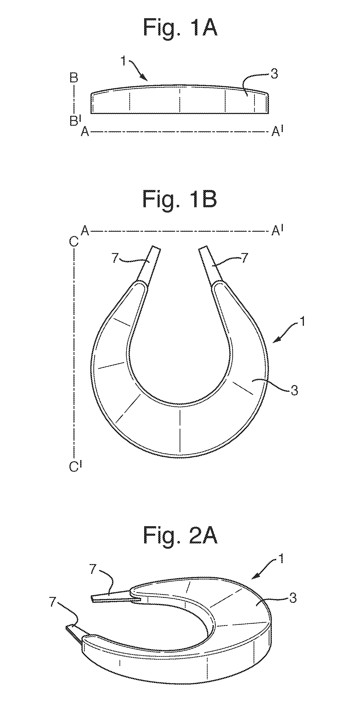
[0045]The sagittal, coronal and horizontal planes are as shown in FIG. 1. With reference to FIG. 1A, line A-A′ lies in the sagittal plane and line B-B′ lies in the coronal plane. With reference to FIG. 1B line A-A′ lies in the sagittal plane and line C-C′ lies in the horizontal plane. Lines A-A′ , B-B′ and C-C′ are mutually perpendicular.

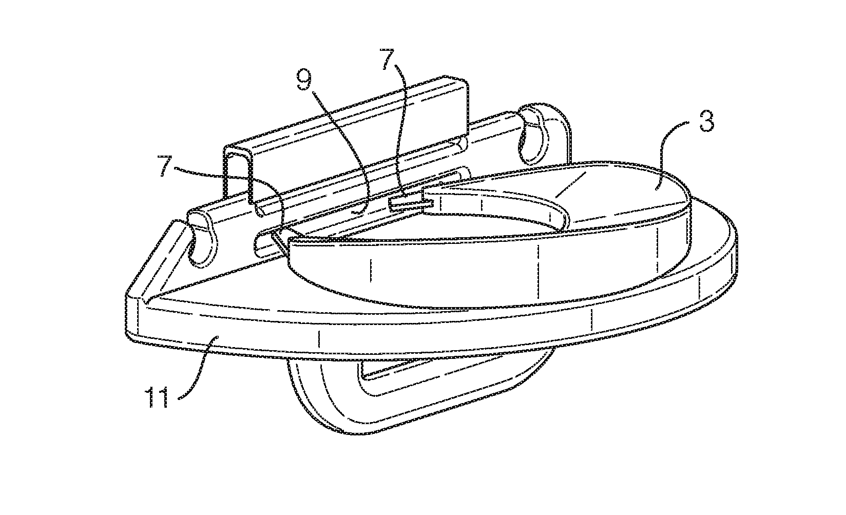
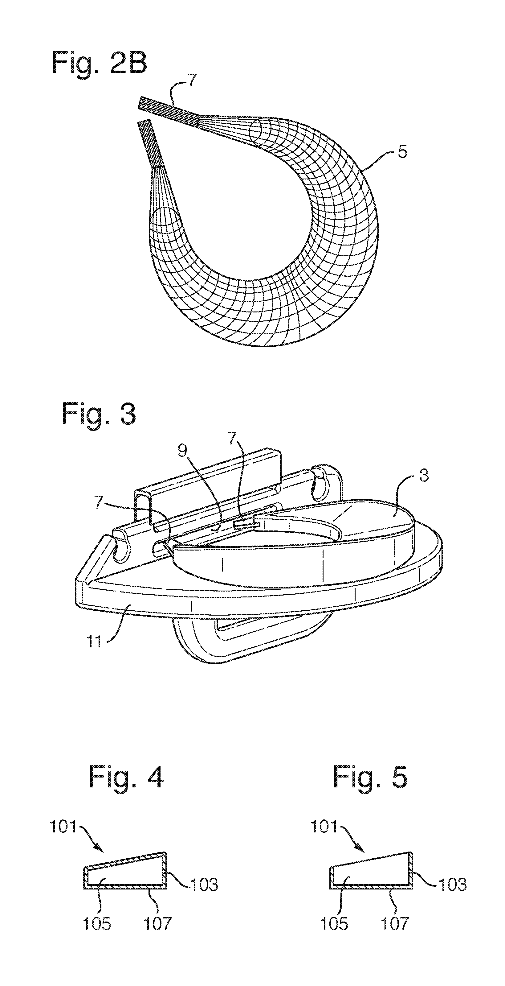
[0046]An embodiment of the invention provides a bearing 1 for use in a total or partial joint replacement prosthesis 11. FIG. 2A shows an exterior view of an embodiment of bearing 1, and FIG. 2B shows an arrangement of the reinforcing element 5 and the attachment member 7 only. The bearing 1 consists of a body 3 and a reinforcing element 5, wherein the reinforcing element 5 extends out of the body 3 of the bearing 1 to form an attachment member 7.

[0047]The body 3 of the bearing is shaped so as to provide support for the artificial and / or natural element of the joint into which it is to be inserted, ideally such that the bearing 1 is fully congruent ...


PUM


Abstract

A bearing for a total or partial joint replacement prosthesis: the bearing having a body and a reinforcing element which strengthens the bearing and which forms an attachment member, and / or the bearing being formed at least partially from polymeric or composite material the bearing comprising a lower modulus portion and a higher modulus portion, one portion of the bearing being at least partially encased by the other portion of the bearing. Also provided is a method for of forming the bearing, and a total or partial joint replacement prosthesis comprising the hearing.

Description

[0001]The invention relates to an at least partially flexible bearing for a prosthetic or natural joint. The bearing may achieve fully comment contact throughout the full range of joint movement, and may be anatomically shaped.BACKGROUND[0002]Existing prosthetic joint bearings are often configured to maintain congruent contact with the hones or prosthetics forming the joint throughout the range of joint movement.[0003]In order to maintain congruent contact, it is often necessary for the bearings to take a non-anatomical shape. This is because previous anatomically shaped prosthetic bearings have not been suitable for maintaining congruent contact throughout the range of joint movement, as they are not able to mimic the natural flexibility of cartilage white remaining rigid enough to support the joint adequately.[0004]An aim of the present invention is to allow the use of anatomical components and a congruent bearing In a low wear bearing combination. The bearing may achieve fully co...

Claims


Application Information

Patent Timeline
Patent Type & Authority Applications(United States)
IPC IPC(8): A61F2/38A61F2/30
CPCA61F2/389A61F2/3872A61F2/30965A61F2240/002A61F2002/3038A61F2002/30481A61F2002/30014A61F2002/30331A61F2002/30576A61F2002/30919A61F2002/30971
Inventor KHAN, MOHAMMED IMRANLLOYD, RUSSELLMURRAY, DAVID WYCLIFFEDODD, CHRISTOPHERO'CONNOR, JOHN
Owner BIOMET UK
Learn More