
Multiple frequency transponder with a single antenna

Active Publication Date: 2017-01-12
ASSA ABLOY AB
View PDF4 Cites 11 Cited by
  • Summary
  • Abstract
  • Description
  • Claims
  • Application Information

AI Technical Summary

Benefits of technology

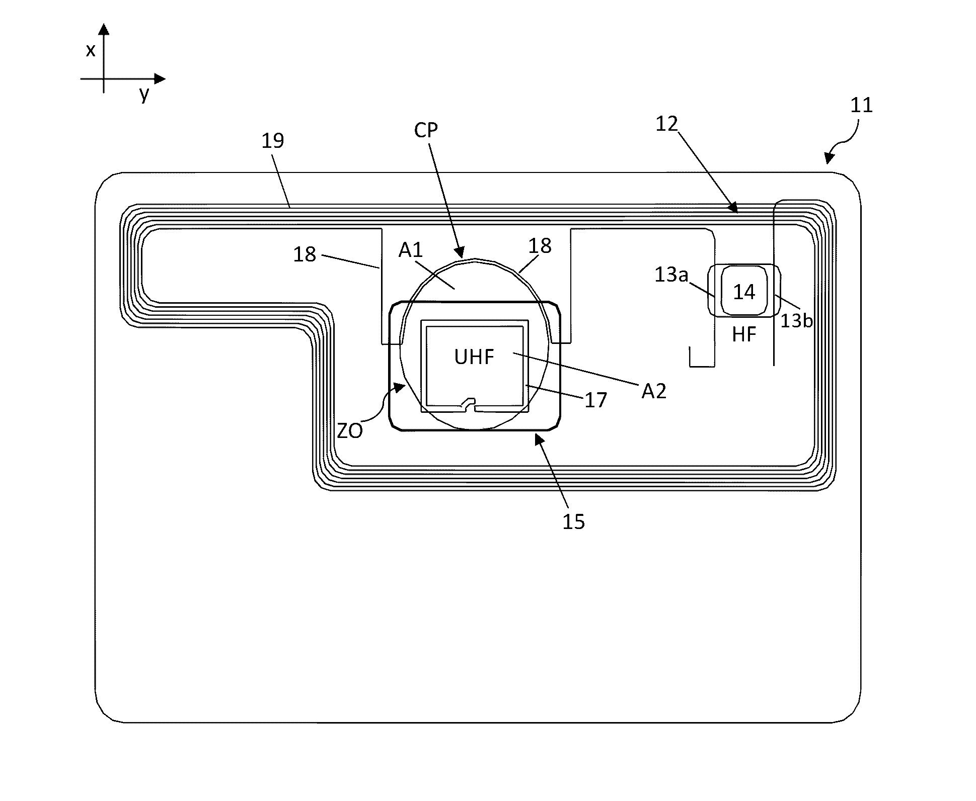
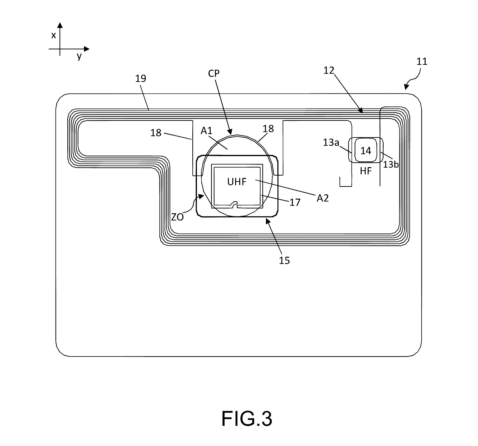
The present invention aims to improve existing devices and proposes a transponder that can function in multiple modes. The transponder includes an RFID chip connected to two antennas. One antenna can be used for HF communication, while the other antenna can be used for UHF communication. The two chips can be used for either HF or UHF communication. The secondary antenna acts as a booster for the UHF chip, and both antennas can form a loop antenna for HF communication. The inductive coupling between the chips allows for separate communication with external readers at different frequencies. The technical effects of the invention are improved functionality and versatility of the transponder.

Problems solved by technology

A key issue of this technology is to find a simple and effective mass production process to manufacture the booster.
The problem is that all elements of the booster have to be tuned accurately in order to obtain the desired transmission characteristic and performance of the whole system (booster+transponder device).
A drawback of this method is that the antenna paths on each side of the sheet have to be connected electrically through the sheet.
. . all imply additional manufacturing steps, most of the time with high technical difficulties and error potential.
This complexity implies lower reproducible and quality yield that are essential drawbacks for mass production.
As one can easily see, this configuration of FIG. 1 is problematic as it covers the entire surface of the card and it is not possible to integrate other technologies in the card.
This configuration is interesting as about half of the card is now free but it has a substantive disadvantage: the HF antenna forms a faraday cage when the electrical circuit is closed and this drastically reduces the performance of the UHF part.
3 cm) which is neither practical nor acceptable.

Method used


Image

  • Multiple frequency transponder with a single antenna
  • Multiple frequency transponder with a single antenna
  • Multiple frequency transponder with a single antenna

Examples


Embodiment Construction

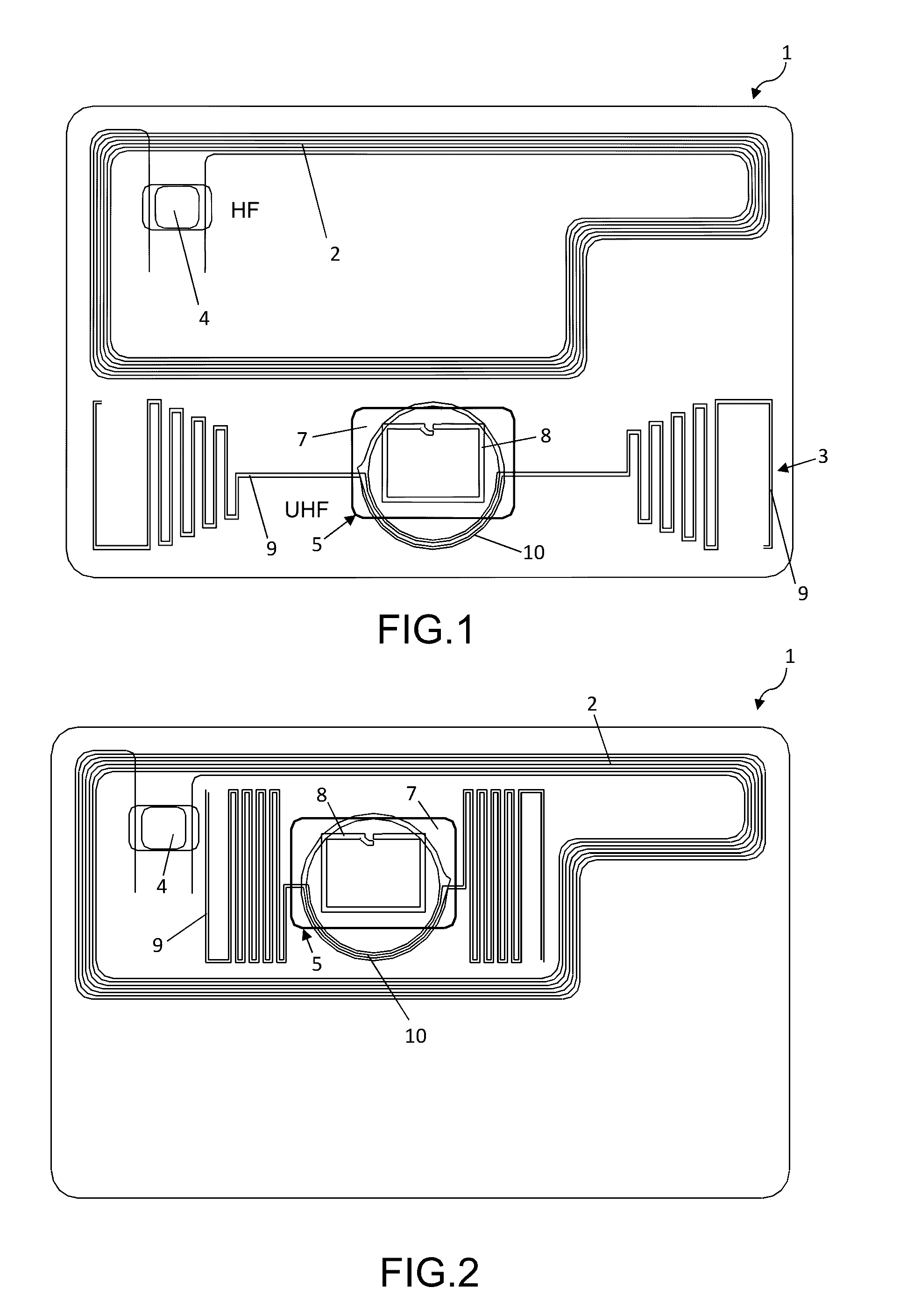
[0042]In FIG. 1, an example of a prior art device is illustrated. It shows an RFID transponder 1, such as a card, comprising two antennas 2, 3, each with a chip or chip module 4, 5. The top antenna 2 with the chip 4 forms an HF communication part and the bottom booster antenna 3 with chip module 5 an UHF communication part.

[0043]The HF chip or chip module 4 is directly connected to the antenna 2, for example by pads or studs.

[0044]The UHF chip or chip module 5 is connected to the antenna 3 via an inductive coupling as described above. More precisely, the chip module 5 comprises a chip 7 electrically connected to a primary antenna 8 which is integrated in / provided with the chip module. The booster antenna 3 comprises a primary dipole UHF antenna 9, showing two symmetrical parts, and a secondary antenna 10 designed to connect inductively with the antenna 8 of the chip module 5 when it is positioned in its proximity.

[0045]As discussed above, FIG. 2 illustrates a second known configurat...


PUM


Abstract

The present invention concerns a RFID transponder, such as a card, comprising a first chip electrically connected to a first antenna and a second chip electrically connected to a second antenna. The first antenna comprises a secondary antenna which is inductively to the second antenna.

Description

CROSS-REFERENCE TO RELATED APPLICATIONS[0001]This application claims the benefit of Swiss National application No. CH00984 / 15 filed Jul. 8, 2015, the entire contents of which are incorporated herein by reference.FIELD OF THE INVENTION[0002]The present invention concerns a transponder able to work in several frequency modes, for example in high frequencies (HF) and ultra-high frequencies (UHF), and using the principle of a coupling device as described in detail hereunder. The transponder may be, for example, included in a card such as a smart card or payment card, or may be used to form a card such as a smart card or payment card.DISCUSSION OF THE BACKGROUND ART[0003]In the art of RFID, a coupling device for a transponder (such as a RFID transponder) generally comprises a primary antenna configured for long range communication with an external RFID reader and a secondary antenna connected in series, wherein the secondary antenna is configured as such to be inductively coupled to an a...

Claims


Application Information

Patent Timeline
IPC IPC(8): G06K19/077G06K19/07G06K7/10H04B5/00
CPCG06K19/07794H04B5/0081G06K7/10237G06K19/0723H04B5/0062G06K19/07749G06K19/07775G06K19/072G06K19/0724G06K19/07767H04B5/77H04B5/26
Inventor KAPP, HUGO
Owner ASSA ABLOY AB
Learn More