Array antenna apparatus having at least two feeding elements and operable in multiple frequency bands

a technology of array antenna and feeding element, which is applied in the field of array antenna apparatus, can solve the problems of complex structure, mobile radio apparatus cannot simultaneously the antenna device cannot implement a plurality of states, etc., and achieve the effect of ensuring sufficient isolation, simple configuration and sufficient isolation between feeding elements

a technology of array antenna and feeding element, which is applied in the field of array antenna apparatus, can solve the problems of complex structure, mobile radio apparatus cannot simultaneously the antenna device cannot implement a plurality of states, etc., and achieve the effect of ensuring sufficient isolation, simple configuration and sufficient isolation between feeding elements

US20080174508A1Active Publication Date: 2008-07-24PANASONIC INTELLECTUAL PROPERTY CORP OF AMERICA

Image

  • Array antenna apparatus having at least two feeding elements and operable in multiple frequency bands
  • Array antenna apparatus having at least two feeding elements and operable in multiple frequency bands
  • Array antenna apparatus having at least two feeding elements and operable in multiple frequency bands

Examples


first preferred embodiment

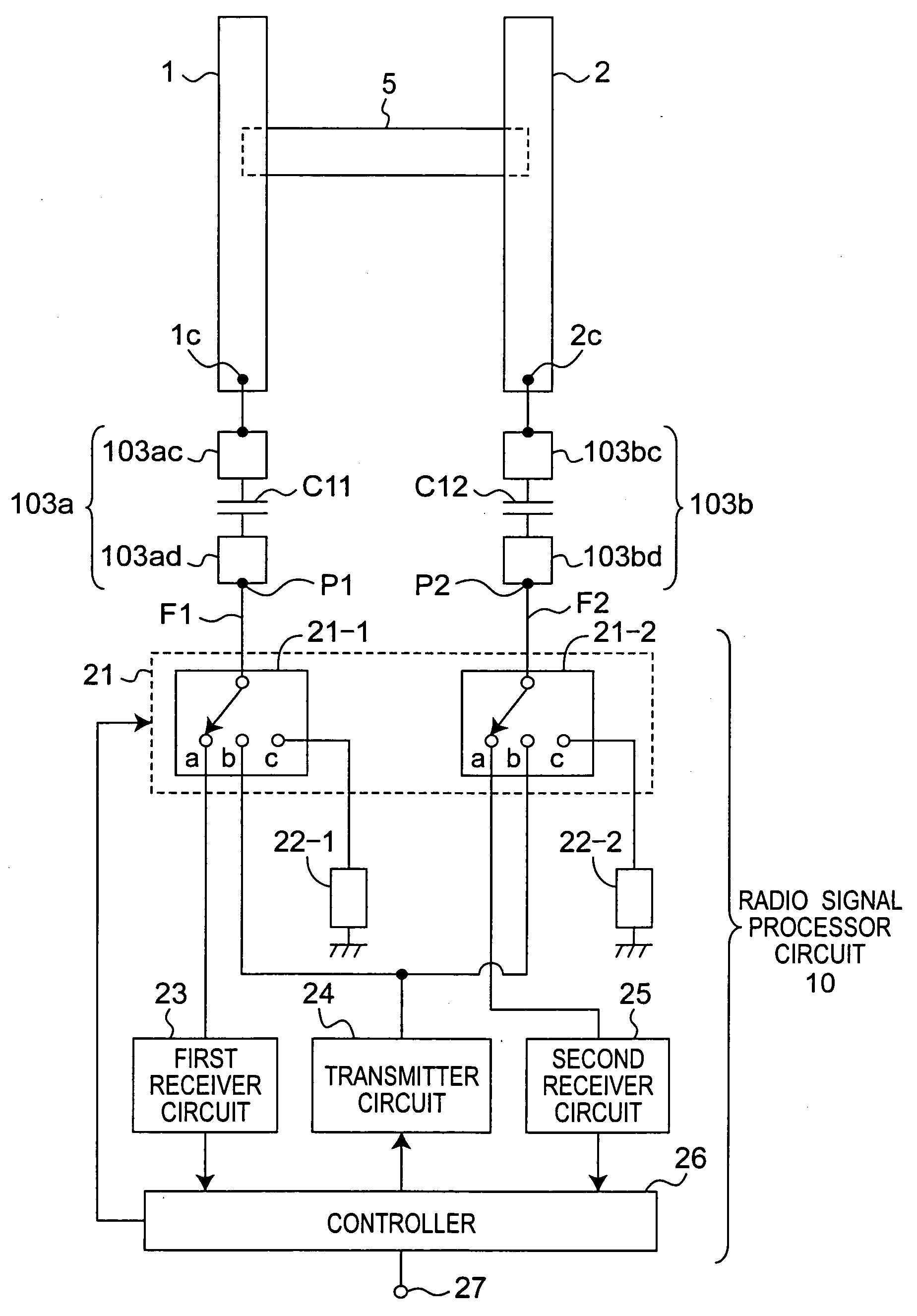
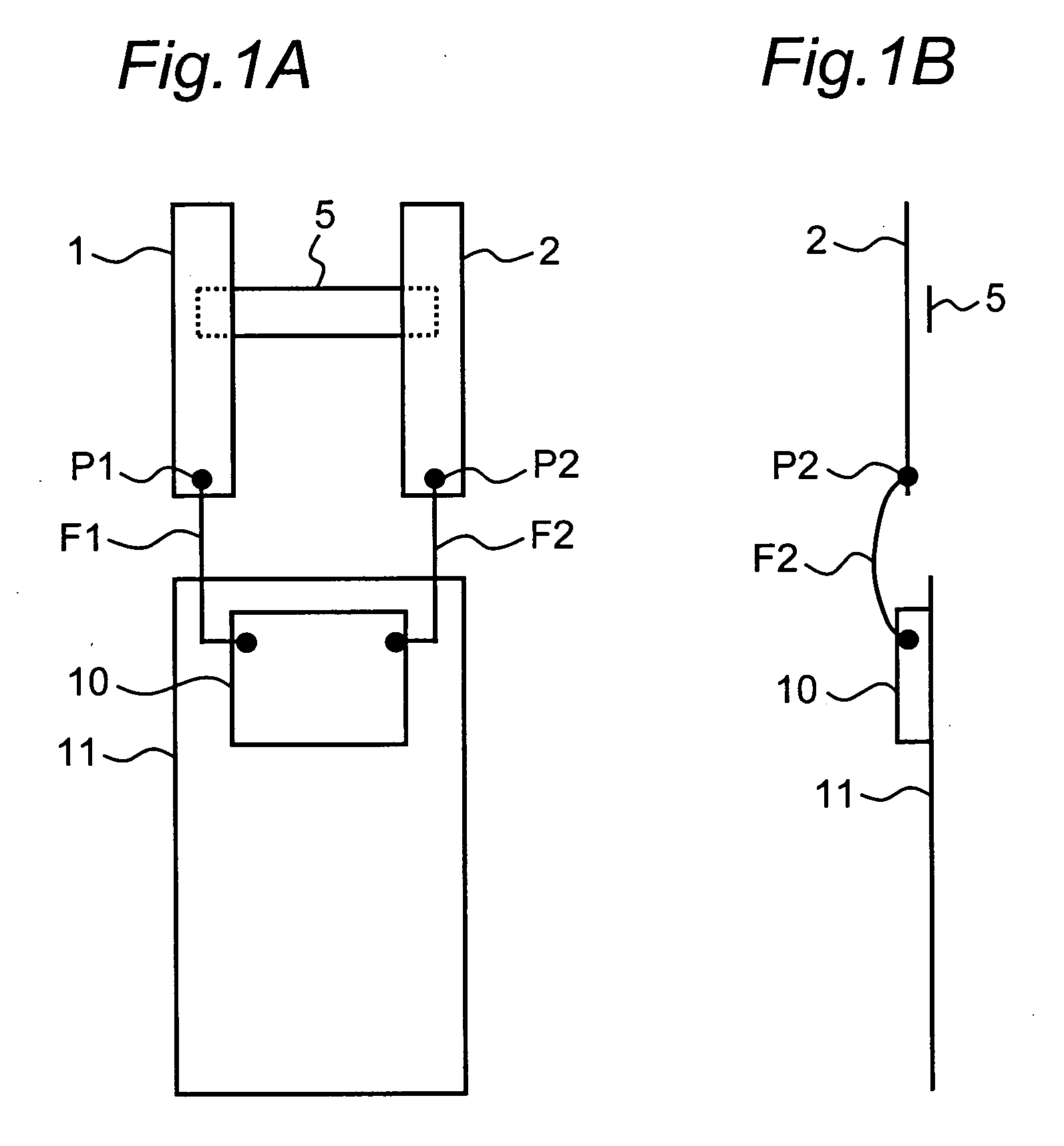
[0083]FIG. 1A is a front view showing a schematic configuration of an array antenna apparatus according to a first preferred embodiment of the present invention, and FIG. 1B is a side view thereof. The array antenna apparatus of the present preferred embodiment is characterized in that the array antenna apparatus includes two feeding elements 1 and 2, and a parasitic element 5 capacitively coupled to the respective feeding elements 1 and 2, and that when operating in a higher frequency band, the apparatus performs MIMO communication by independently exciting the feeding elements 1 and 2; on the other hand, when operating in a lower frequency band, the apparatus performs communication by exciting the feeding element 1, the parasitic element 5 and the feeding element 2, which are capacitively coupled to each other, as a loop antenna.

[0084]In FIGS. 1A and 1B, the array antenna apparatus includes the feeding elements 1 and 2 each made of a rectangular conductive plate, and the feeding e...

second preferred embodiment

[0111]FIG. 16A is a front view showing a schematic configuration of an array antenna apparatus according to a second preferred embodiment of the present invention, and FIG. 16B is a side view thereof. An array antenna apparatus according to preferred embodiments of the present invention is not limited to the one having the configuration including two feeding elements 1 and 2 as shown in FIGS. 1A and 1B, and the array antenna apparatus may include three or more feeding elements.

[0112]In FIGS. 16A and 16B, the array antenna apparatus includes feeding elements 1, 2 and 3 each made of a rectangular conductive plate, and the feeding elements 1, 2 and 3 are provided so as to be in the same plane and spaced apart by a certain distance from each other. Furthermore, a parasitic element 5E made of a rectangular conductive plate is provided in a plane spaced apart by a certain distance from the plane where the feeding elements 1, 2 and 3 are provided, so as to be close to the feeding elements ...


PUM


Abstract

An array antenna apparatus includes a first feeding element having a first feed point, a second feeding element having a second feed point, and a first parasitic element electrically connected to the respective first and second feeding elements. In a first frequency band, respective resonances in the feeding elements occur independent of each other, by eliminating electromagnetic mutual coupling between the feeding elements, and exciting the first feeding element through the first feed point as well as exciting the second feeding element through the second feed point. In a second frequency band lower than the first frequency band, a loop antenna having a certain electrical length is formed by the first and second feeding elements and the first parasitic element, and a resonance of the loop antenna substantially occurs by exciting the first feeding element through the first feed point.

Description

BACKGROUND OF THE INVENTION[0001]1. Field of the Invention[0002]The present invention relates to an array antenna apparatus, mainly for mobile communication, having at least two feeding elements and operable in multiple frequency bands, and relates to a wireless communication apparatus provided with this array antenna apparatus.[0003]2. Description of the Related Art[0004]The size and thickness of portable wireless communication apparatuses, such as mobile phones, have been rapidly reduced. Portable wireless communication apparatuses have been transformed from apparatuses to be used only as conventional telephones, to data terminals for transmitting and receiving electronic mails and for browsing web pages of WWW (World Wide Web), etc. Further, since the amount of information to be handled has increased from that of conventional audio and text information to that of pictures and videos, a further improvement in communication quality is required. In such circumstances, an array anten...

Claims


Application Information

Patent Timeline
24 Jul 2008
Publication
US20080174508A1
IPC
H01Q1/50; H01Q1/24; H01Q7/00; H01Q9/30; H01Q21/28; H01Q21/30; H04B7/04
CPC
H01Q9/30; H01Q5/321; H01Q1/521; H01Q21/28
Inventors
IWAI, HIROSHI; YAMAMOTO, ATSUSHI