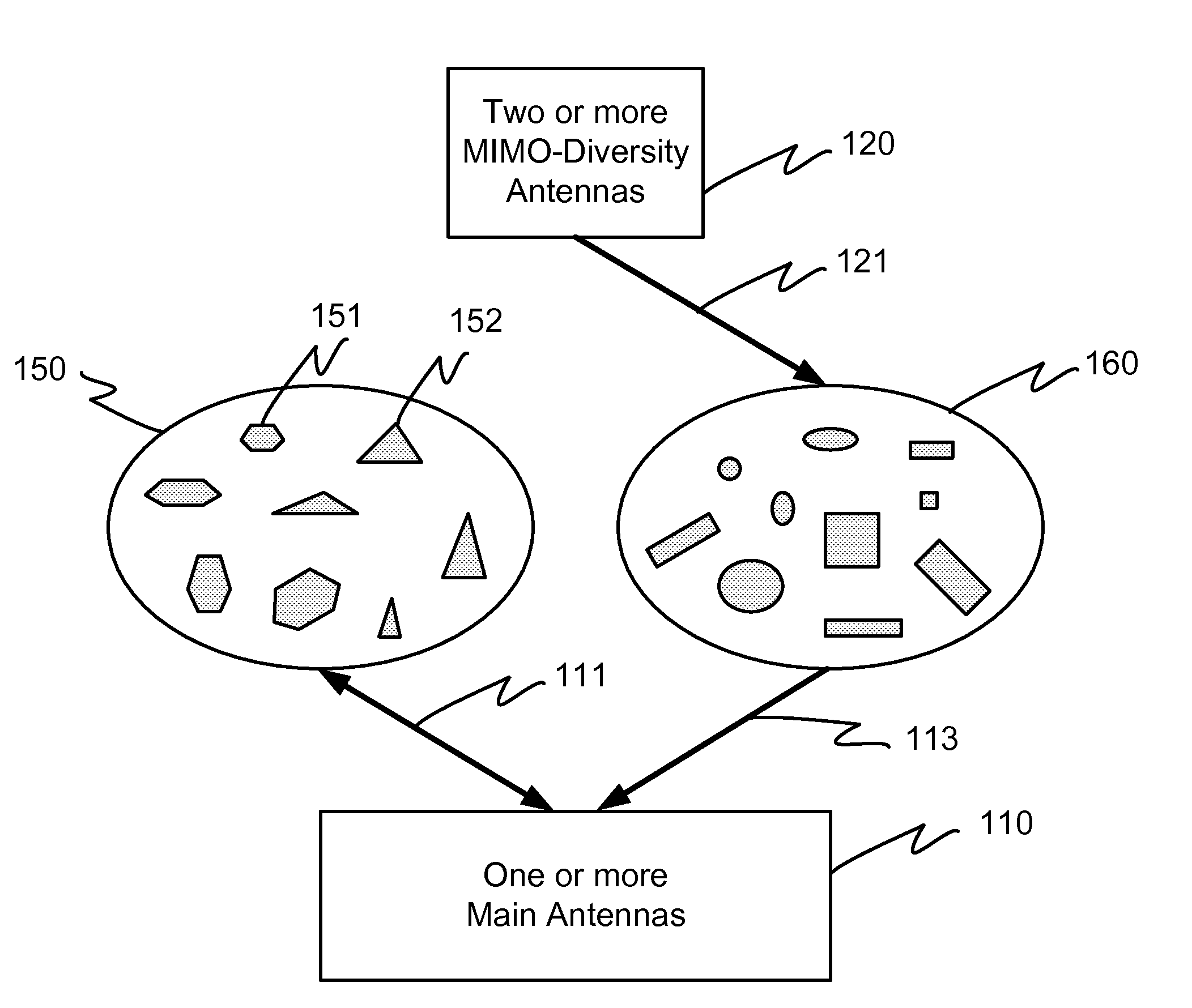
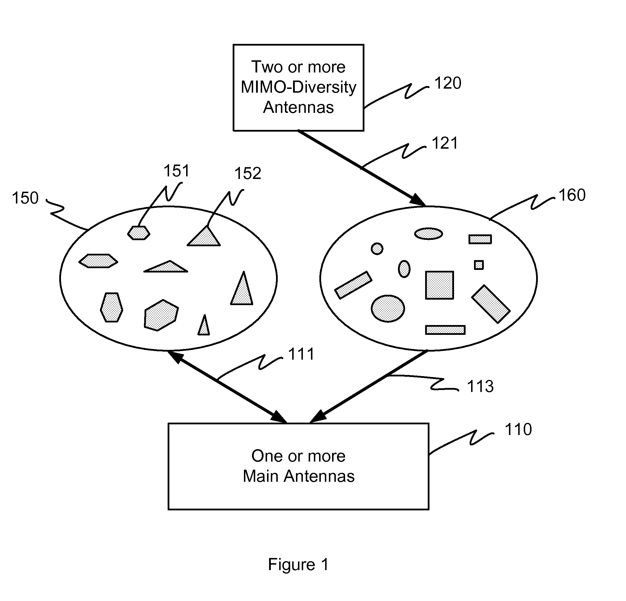
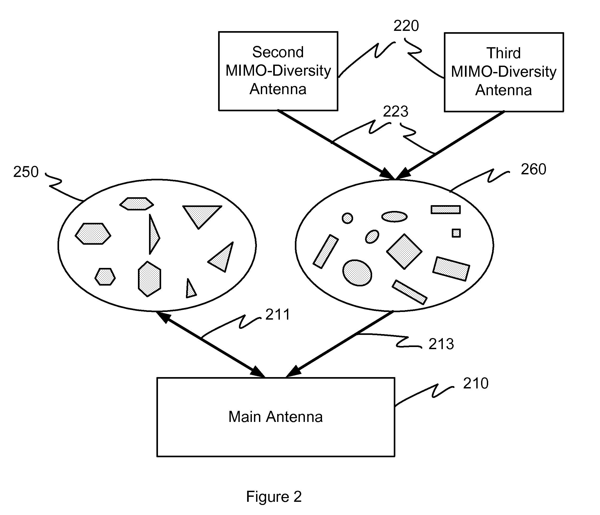
Multiple antenna system for wireless communication
a multi-antenna system and wireless communication technology, applied in the field of wireless communication systems, can solve the problems of complex design, large main antenna footprint, and difficulty in implementing diversity or mimo schemes
- Summary
- Abstract
- Description
- Claims
- Application Information
AI Technical Summary
Benefits of technology
Problems solved by technology
Method used
Image
Examples
example 1
[0081]This example is directed to an antenna system and associated RF front end for a mobile wireless communications terminal supporting, at least partially, the explicit frequency bands and the communications standards shown in FIGS. 3 and 4, and outlined below. Generally, the acronyms below specify a type of communication standard to be employed as a three- or four-letter acronym, followed by a nominal center frequency to be used. Associated transmit and receive frequency bands currently in use are further listed after each acronym. It is to be understood that the invention may be similarly employed to operate using communication standards and frequency bands other than those listed below.
LTE700: 698-716 MHz Transmit 728-746 MHz ReceiveGSM850: 824-849 MHz Transmit 869-894 MHz ReceiveUMTS850: 824-849 MHz Transmit 869-894 MHz ReceiveGSM900: 880-915 MHz Transmit 925-960 MHz ReceiveUMTS900: 880-915 MHz Transmit 925-960 MHz ReceiveLTE900: 880-915 MHz Transmit 925-960 MHz ReceiveGSM1800...
example 2
[0092]For the frequency bands and communications standards of FIG. 4, the number of frequency bands that require support of MIMO-diversity reception include three higher frequency bands, i.e., 1930-1990 MHz, 2110-2155 MHz and 2110-2170 MHz and three lower frequency bands, i.e., 728-746 MHz, 869-894 MHz and 925-960 MHz. As such, this example is directed to an antenna system and RF front end that supports MIMO-diversity reception at least partially in the bands of FIG. 4, and is implemented using multi-resonant narrow-band MIMO-diversity antennas that are reconfigurable.
[0093]In some embodiments, the MIMO-diversity antennas may be simplified as a higher frequency band requiring MIMO reception is virtually the same the world over, and two lower frequency bands requiring MIMO reception are relatively close together and only one of those is in use in any region of the world. For example and with reference to FIG. 3, MIMO-diversity reception is required on three of the defined receive ban...
example 3
[0109]FIG. 11 shows an exemplary design of a RF front-end and an antenna system configured to provide MIMO-diversity reception with an arbitrary number (m>2) of MIMO-diversity receive paths, for a second set of configurations consisting of an arbitrary number (n2) of configurations, according to embodiments of the invention. The antenna system is also configured to provide non-diversity reception for a first set of configurations comprising an arbitrary number (n1) of configurations.
[0110]A main antenna 1110 supports transmission in all (n1+n2) configurations of the first set and second set of configurations. These transmit paths utilize (n1+n2) power amplifiers (PA) 1112, as shown in the bottom end of FIG. 11. The first set of n1 configurations do not require MIMO-diversity reception and are also supported by the main antenna 1110. The second set of n2 configurations require MIMO-diversity reception, provided by the m MIMO-diversity antennas 1120 with corresponding m receive paths....
PUM
 Abstract
Description
Claims
Application Information
 - R&D
- Intellectual Property
- Life Sciences
- Materials
- Tech Scout
- Unparalleled Data Quality
- Higher Quality Content
- 60% Fewer Hallucinations
Browse by: Latest US Patents, China's latest patents, Technical Efficacy Thesaurus, Application Domain, Technology Topic, Popular Technical Reports.
© 2025 PatSnap. All rights reserved.Legal|Privacy policy|Modern Slavery Act Transparency Statement|Sitemap|About US| Contact US: help@patsnap.com


