Back Mounted Flight Machine

Active Publication Date: 2017-01-19
TYLER NELSON +1
View PDF5 Cites 7 Cited by
  • Summary
  • Abstract
  • Description
  • Claims
  • Application Information

AI Technical Summary

Benefits of technology

The present invention is a flight device that allows for adjustment of the engine and motor positions as fuel is burned, so that changes in the center of gravity can be more easily dealt with by the pilot. The high pivot point allows for fine control and positioning of the engines and fuel tank, and the nature of the connection allows for relative movement between the harness and the frame in many orientations, so that improved control of the flight device can potentially be achieved.

Problems solved by technology

An enduring issue with these flight devices relates to control and reduction of weight, as well as the amount of fuel stored and burned, so that the pilot is able to remain airborne for more than just short periods of time.

Method used


Image

  • Back Mounted Flight Machine
  • Back Mounted Flight Machine
  • Back Mounted Flight Machine

Examples


Embodiment Construction

[0053]Reference is now made to the drawings. The figures accompanying this application show various aspects of a jet pack or back and shoulder mounted flight machine in accordance with different embodiments of the present invention.

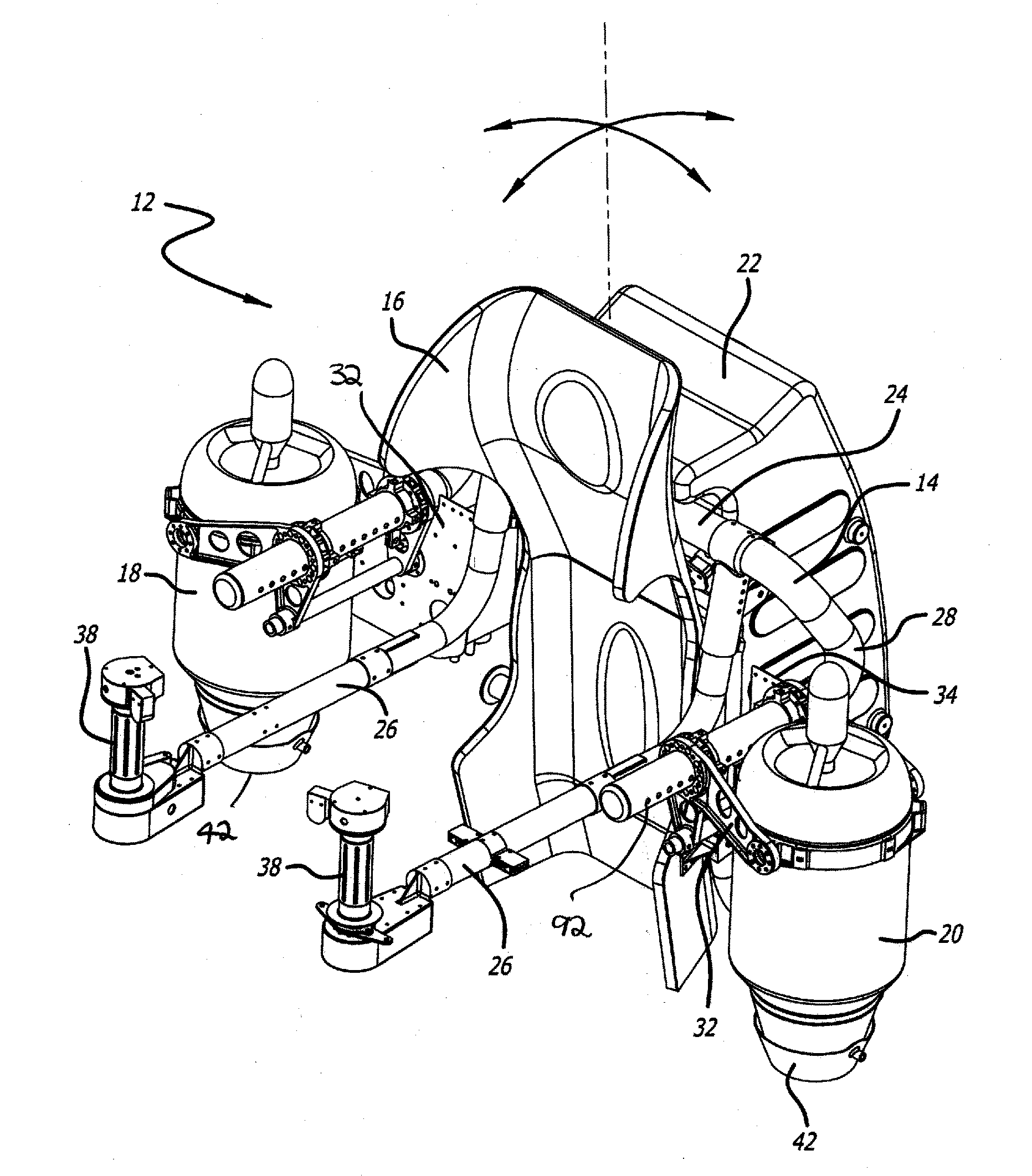
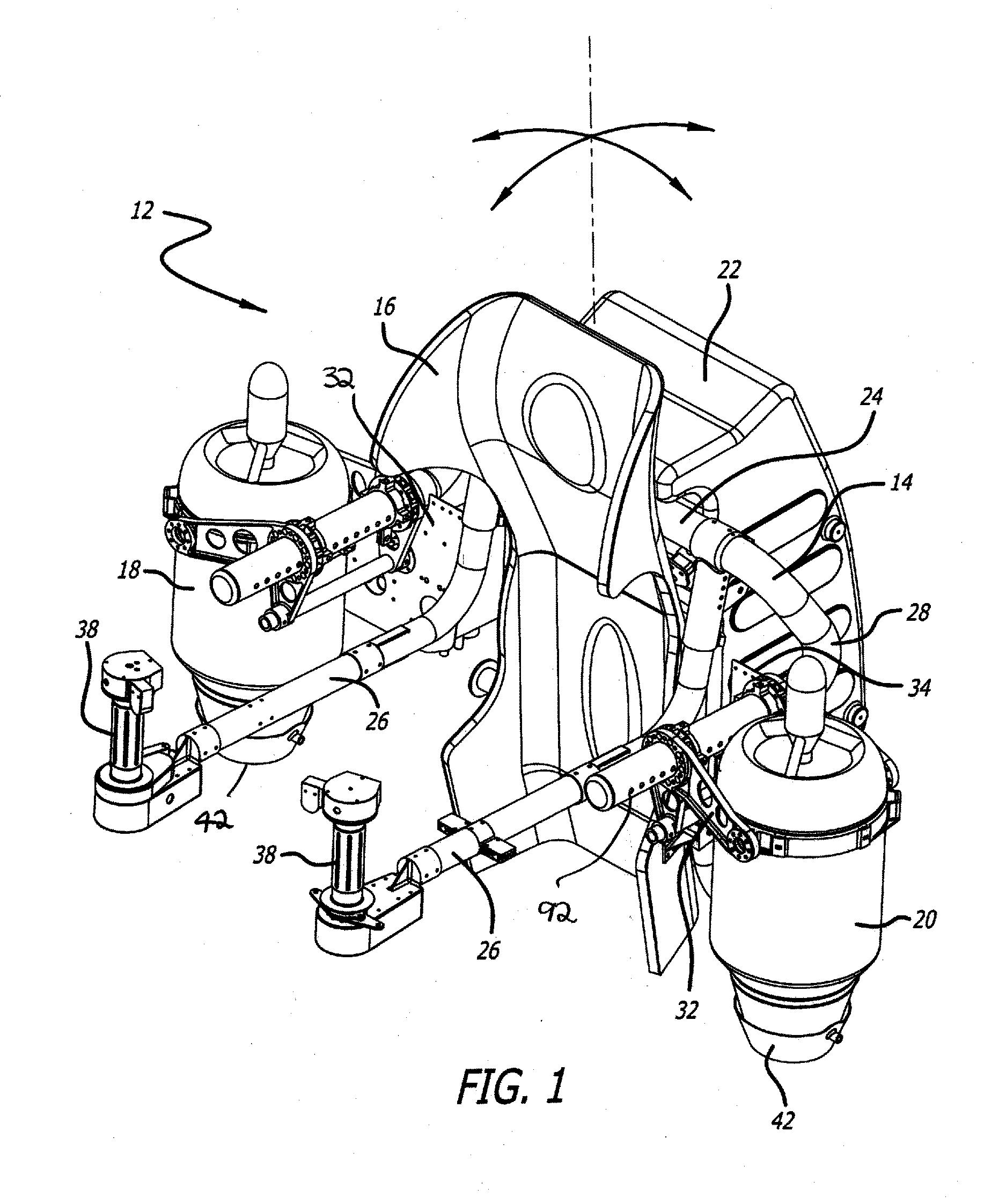
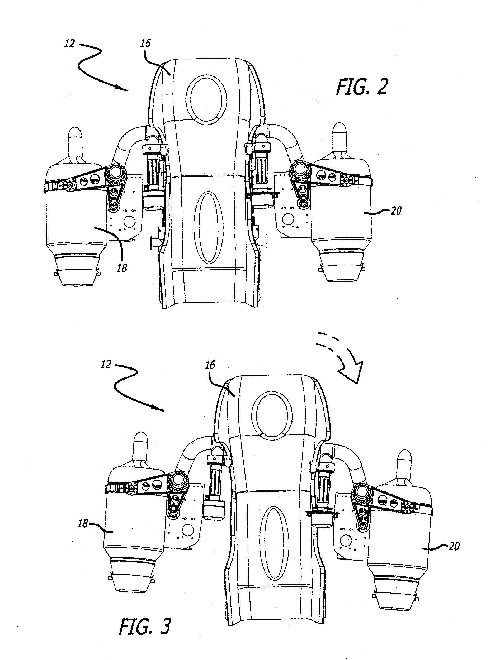
[0054]FIGS. 1 to 12 show one embodiment of the invention, showing a jet pack or back mounted flight machine 12. The jet pack comprises a frame 14, a harness 16 attached to the frame 14, as well as a pair of laterally placed engines 18 and 20, also attached to the frame 14. Further, a fuel tank 22 is connected to the frame 14.

[0055]The frame 14 includes a rear generally horizontal bracket 24, attached to the harness 16 as will be described, a pair of control arms 26, and a pair of engine mounting arms 28. The engine mounting arms 28 each have attached thereto one of the engines 18 or 20. As will be seen in the figures, the engines 18 and 20 are attached to the engine mounting arms 28 by a pair of brackets 32 and 34, and these brackets 32 and 34 cooperate w...


PUM


Abstract

A back mounted flight machine comprises a frame comprising a connecting bracket, a pair of lateral arms extending from the connector bracket, and an engine mounted on each of the lateral arms in a selected position. A harness is mounted on the connecting bracket of the frame between the pair of lateral arms. Further, a fastening mechanism is provided for connecting the harness to the connecting bracket to permit relative movement between the harness and the frame in a plurality of orientations.

Description

CROSS REFERENCE TO RELATED APPLICATIONS[0001]This application claims the benefit of U.S. Provisional Patent Application No. 62 / 185,178 filed Jun. 26, 2015, U.S. Provisional Patent Application No. 62 / 249,794 filed Nov. 2 2015, and U.S. Provisional Patent Application No. 62 / 293,290 filed Feb. 9, 2016, all of which are incorporated herein in their entirety.FIELD AND BACKGROUND OF THE INVENTION[0002]This invention relates to a back mounted flight machine. Such a machine is sometimes also referred to as a jet pack, and comprises a harness which is attached to the back and shoulders of a user or pilot, the harness supporting a frame for engines, controls, fuel tanks and other components.[0003]The back mounted flight machine in accordance with the invention attaches to the user or pilot. The user or pilot is able through various mechanisms of control to orient the machine in different positions so as to determine and regulate the direction of flight, or enable the machine to substantially ...

Claims


Application Information

Patent Timeline
IPC IPC(8): B64C39/02B64D17/00B64D33/08B64D27/16B64D27/24B64D37/04B64C15/12
CPCB64C39/026B64D37/04B64D17/00B64D33/08B64D27/16B64D27/24B64C15/12B64D17/40
Inventor TYLER, NELSONMAYMAN, DAVID
Owner TYLER NELSON
Why Eureka
Try Eureka