Winding-up screen device

a screen device and window screen technology, applied in the direction of door/window protective devices, shutters/movable grilles, insect protection, etc., can solve the problems of poor outward appearance, damage to the opening frame, damage to the external appearance, etc., and achieve the effect of narrowing the width and height of the opening, and being long and bendabl

Inactive Publication Date: 2007-02-22
SEIKI HANBAI CO LTD
View PDF7 Cites 24 Cited by
  • Summary
  • Abstract
  • Description
  • Claims
  • Application Information

AI Technical Summary

Benefits of technology

[0008] In this way, according to the winding-up screen device of the present invention, when the screen is wound around the winding axis to make the opening portion open, since the screen guide for guiding the end portion of the screen unwound from a winding axis is housed in the inner portion of the fixed frame or the movable frame and not left on the opening frame, the screen guide does not harm the external appearance and narrow the width and height of the opening, and accordingly, does not produce a problem to go in and out of a room through the opening frame.
[0011] Furthermore, in the winding-up screen device, one end of the screen guide is fixed to the fixed frame and the screen guide goes in and out of the inner portion of the movable frame with the forward and backward movement of the movable frame, and wherein one end of the screen is held in the movable frame, and the winding axis holding the other end of the screen and winding the screen may be supported in the inner portion of the fixed frame so as to be rotational, or one end of the screen guide is fixed to the movable frame and the screen guide goes in and out of the inner portion of the fixed frame with the forward and backward movement of the movable frame, and one end of the screen is held in the fixed frame and the winding axis holding the other end of the screen and winding the screen may be supported in the inner portion of the movable frame so as to be rotational. Then, it is desirable that the guide part contain a concave groove sitting astride a guide rail provided in a protruding condition on the opening frame on the surface opposite to the inner surface so as to freely slide and that the screen guide led out on the opening frame be guided by the guide rail, because the slide operation of the screen guide is more stabilized.
[0012] Moreover, in the winding-up screen device, the screen is opened and closed by horizontal movement of the movable frame and the screen guide can be led out along the lower edge portion of the screen unwound from the winding axis. At this time, the screen device may be constructed in such a way that a slide part is contained at the upper end of the movable frame and the movable frame is suspended from a slide frame fixed to the upper frame of the opening frame by using the slide part so as to freely slide. However, it is possible that the screen guide may led out along both edge portions of the screen unwound from the winding axis.

Problems solved by technology

Now, in such a winding-up screen device, since a gap is easily formed between both end portions of the screen unwound from a winding axis and an opening frame of a building, not only the outward appearance is poor, but also insects such as mosquitoes, flies, etc., easily enter the room through the gap particularly when the screen is an insect prevention net.
However, in such a winding-up window screen device disclosed in the above patent document, it is required to fix the rail having a groove for guiding the edge portion of an insect prevention net to the opening frame of a building and accordingly, even if the insect prevention net is wound around a winding axis to make the opening portion open, the rail having a groove is left on the opening frame and the external appearance is harmed.
Moreover, when the above winding-up window screen device is used as a vertical opening type in which the opening and closing operation is performed upward and downward, the opening width is narrowed as much as the height of the rail, and, when it is used as a horizontal opening type in which the opening and closing operation is performed in the horizontal direction, the opening height is narrowed as much as the height of the rail and a difference in level because of the rail is formed on the floor where the lower frame of the opening frame is formed which may cause an obstacle when going in and out of a room through the opening frame is performed.

Method used


Image

  • Winding-up screen device
  • Winding-up screen device
  • Winding-up screen device

Examples


first embodiment

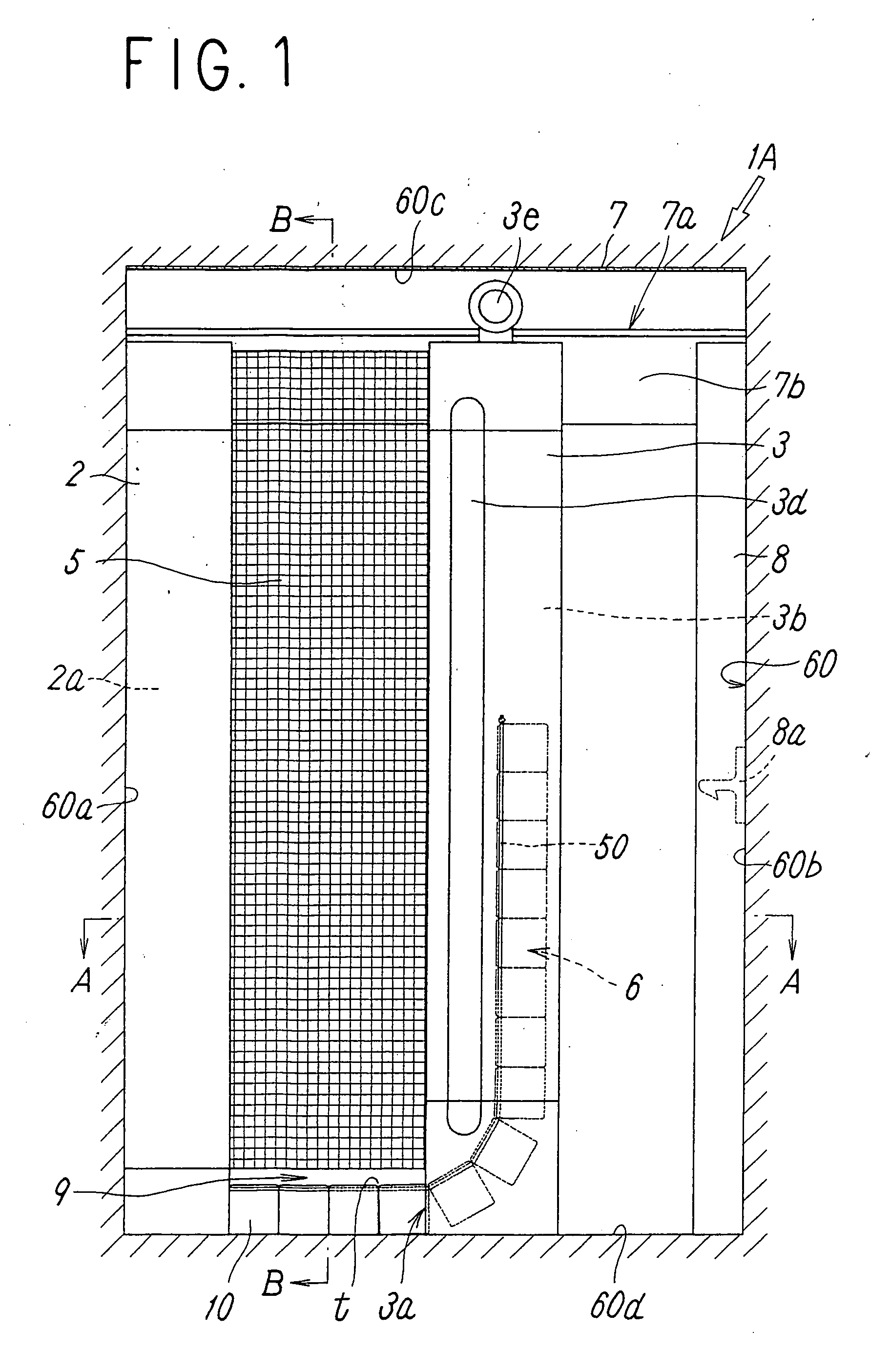
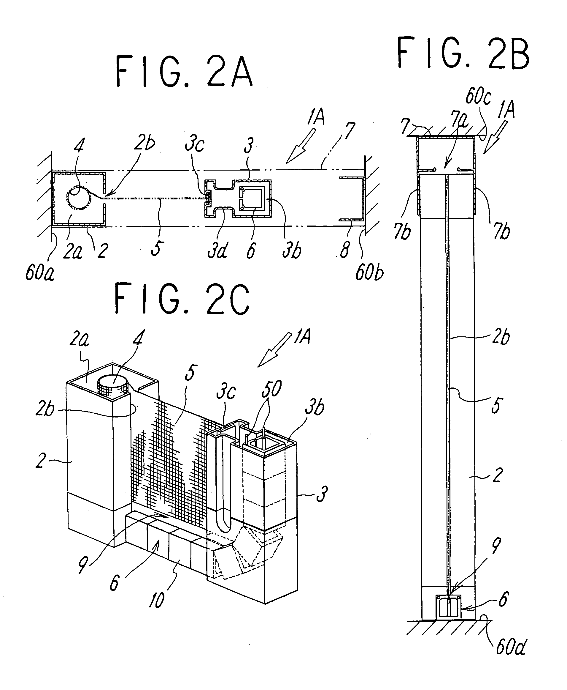
[0037] First, the winding-up screen device according to the present invention is described based on FIG. 1 and FIGS. 2a to 2c. A winding-up screen device 1A, which is attached to an opening frame 60 made up of a pair of vertical frames 60a and 60b and a pair of upper and lower frames 60c and 60d as in a window frame, an entrance and exit, etc., in a building and is opened and closed sideways, contains a fixed frame 2 to be fixed to one vertical frame 60a of the opening frame 60, a movable frame 3 parallel to the fixed frame 2 and movable back and forth between the pair of vertical frames 60a and 60b, the screen 5 wound around a winding axis 4 inside the fixed frame 2, extended between the fixed frame 2 and the movable frame 3, and opened and closed in such a way that the screen 5 is wound around the winding axis 4 and unwound from that with the forward and backward operation of the movable frame 3, a screen guide 6 going in and out of the movable frame 3 with the forward and backwar...

second embodiment

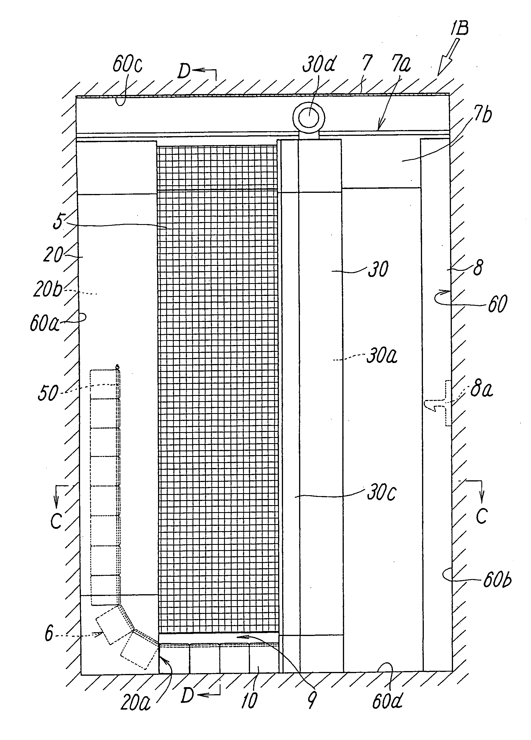
[0053] The main difference of the screen device 1B of the second embodiment from the screen device 1A is in that one end of the screen guide 6 is fixed to the lower end portion of a movable frame 30 and the screen guide 6 goes in and out of the inner portion 20b of the fixed frame 20 through the opening 20a provided in the lower end portion of the fixed frame 2d with the opening and closing operation of the movable frame 30 and that one end in the horizontal direction of the screen 5 is held, the winding axis 4 for winding the screen 5 is supported inside the movable frame 30 so as to be able to be rotated, and the other end in the horizontal direction of the screen 5 is held in the fixed frame 20.

[0054] Concretely, the movable frame 30 is formed so as to be hollow and, in its inner portion 30a, the winding axis 4 is supported so as to be able to be rotated. Then, a slit-shaped opening 30b for putting in and out the screen 5 is provided on the surface facing the fixed frame 20 of th...

third embodiment

[0058] The main difference of the screen device 1C of the third embodiment from the screen device 1A is in that a wiring mechanism 40 in which extended cords 40a and 40b are hung to maintain the fixed frame 2 and the movable frame 3 in parallel with their tension is provided.

[0059] Concretely, one end of a first extended cord 40a is fixed to the inner portion 3b of the movable frame 3, the cord 40a is led to the upper portion of the movable frame 3, the cord 40a makes a turn at the upper end portion of the movable frame 3, the cord 40a is laid to the upper end portion of the latch frame 8 along the upper end portion of the screen device 1C, the cord 40a turns back at the upper end portion of the latch frame 8, the cord 40a is laid to the upper end portion of the fixed frame 2 along the upper end portion of the screen device 1C, the cord 40a makes a turn at the upper end portion of the fixed frame 2, the cord 40a is led to the lower end portion of the inner portion 2a of the fixed fr...


PUM


Abstract

A winding-up screen device in which, when a screen is wound around a winding axis, a screen guide for guiding the edge portion of the screen unwound from the winding axis is not left on the opening frame of a building. A joining groove is provided in the screen guide provided so as to go in and out between an opening frame and a fixed frame or a movable frame of the building, a joining part is attached to the edge portion, to be guided by the screen guide, of a screen, the screen guide goes in and out when the screen is wound and unwound by operation of the movable frame, and the joining part of the unwound screen is joined to the joining groove of the screen guide so as to freely slide.

Description

TECHNICAL FIELD [0001] The present invention relates to a winding-up screen device attached to an opening frame of a building for the purpose of dust resistance, glare protection, heat insulation, mothproof, and others. BACKGROUND ART [0002] Up to now, a winding-up screen device, in which a screen wound around a winding axis is supported between a fixed frame fixed in an opening frame of a building and a movable frame going to and coming back from the fixed frame and opening and closing operation can be performed in such a way that the screen is wound around the winding axis or unwound by the going and coming back movement of the movable frame, is well known. [0003] Now, in such a winding-up screen device, since a gap is easily formed between both end portions of the screen unwound from a winding axis and an opening frame of a building, not only the outward appearance is poor, but also insects such as mosquitoes, flies, etc., easily enter the room through the gap particularly when t...

Claims


Application Information

Patent Timeline
Patent Type & Authority Applications(United States)
IPC IPC(8): E06B9/06E06B9/54E06B9/58
CPCE06B2009/543E06B9/54E06B3/92E06B9/52E06B9/56
Inventor CHINO, MITSUHIKOKAMOSAWA, YOJITODA, HIROTSUGU
Owner SEIKI HANBAI CO LTD
Why Eureka
Try Eureka