
Band Tensioning Tool and Calibration Device Therefor

a band tensioning and tool technology, applied in the field of relatively compact band tensioning tools, can solve the problems of reducing the effectiveness of the tie, reducing the service life of the tie, so as to improve the service life, maintain the tension of the band, and improve the effect of the head stiffness

Active Publication Date: 2017-01-19
BAND IT IDEX
View PDF3 Cites 3 Cited by
  • Summary
  • Abstract
  • Description
  • Claims
  • Application Information

AI Technical Summary

Benefits of technology

The present invention provides a knife with an arcuate cutting edge and a head deformation edge. The cutting edge is used to sever a band and the deformation edge is used to deform the cable tie's locking feature, which increases the cable tie's retained force. The knife also removes sharp corners and provides a smooth cut for safety. By maintaining tight tolerances between the blade and the knife, thinner cable ties can be formed and severed without bending. The blade has an integrated knife housing that slidingly receives the knife, reducing damaging loads acting on the blade and maintaining the tolerance between the blade and the knife edge after many uses.

Problems solved by technology

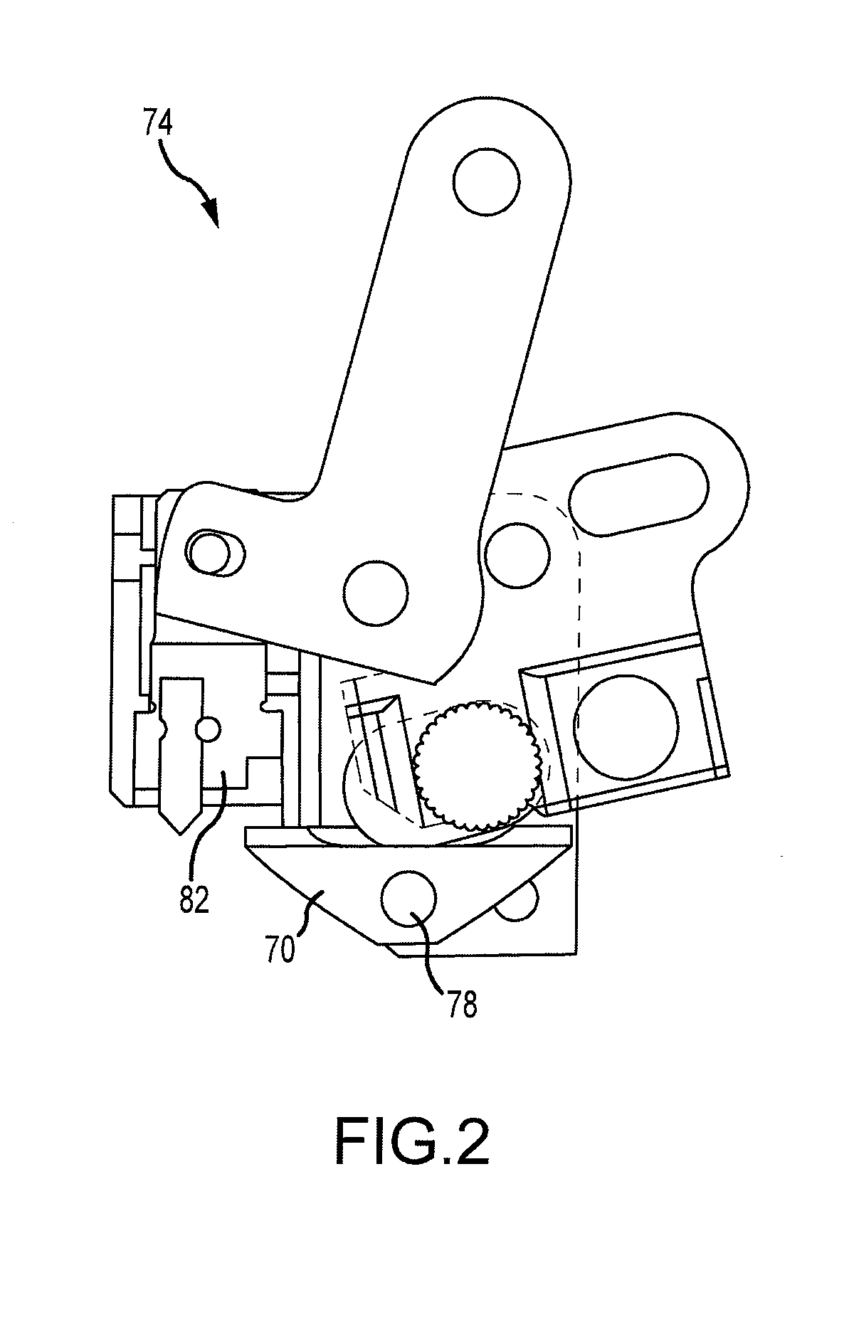
Forces will also be transmitted through the pin 78 to the sidewalls of the tool head, which often weakens or damages the same.
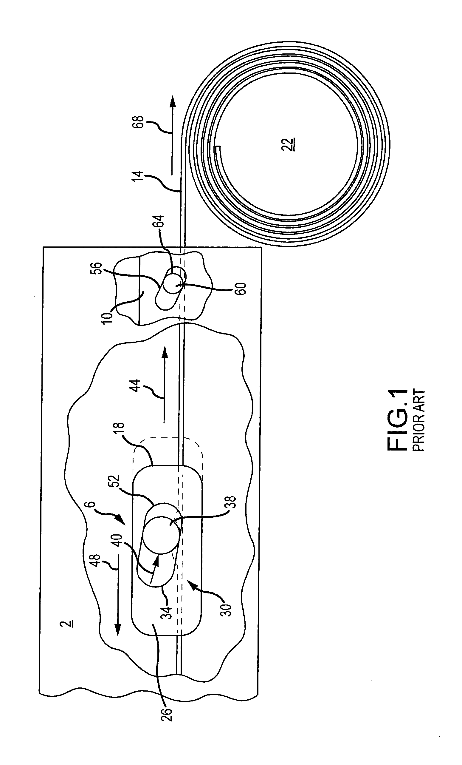
One drawback of prior art tensioning tools is that downward pressure from the knife is transmitted through the band and to the blade, which stresses the blade and adversely affects its effectiveness.
Band cutting is also adversely affected because the blade edge is spaced from the blade's attachment point, i.e., the location where pressure acting on the blade's cutting edge is reacted.
Over time, the blade may be prone to flex, which can lead to fatigue and ultimately failure.
Unfortunately, the failure rate and mode is unpredictable, wherein the blade may fail after 100, 200, or 1000 bands are tensioned.
When blades fail, the tools are shipped from the end user to the factory for blade or knife replacement, which is expensive, costly, and time consuming.
As alluded to above, blade support of prior art tools is not ideal and blade damage is common.
The primary failure mode is blade edge degradation and, in some instances, fracture.
This complex design came from a desire to provide a blade with two edges such that when one was damaged, the blade could be removed and rotated to locate the previously non-used blade adjacent to the knife.
Another drawback of prior art tensioning tools is that the knife does not travel in a smooth, continuous manner, thus a gap between the knife and the blade is not consistent, which affects cutting performance and can increase blade loads.
For example, if the space between the knife's cutting edge and the blade's cutting edge is too wide, knife travel may be inadequate to sever the band as material will deform between the knife edge in the blade edge.
If the gap is too narrow, excess loads generated by the knife will be transferred to the blade and cause damage.

Method used


Image

  • Band Tensioning Tool and Calibration Device Therefor
  • Band Tensioning Tool and Calibration Device Therefor
  • Band Tensioning Tool and Calibration Device Therefor

Examples


Embodiment Construction

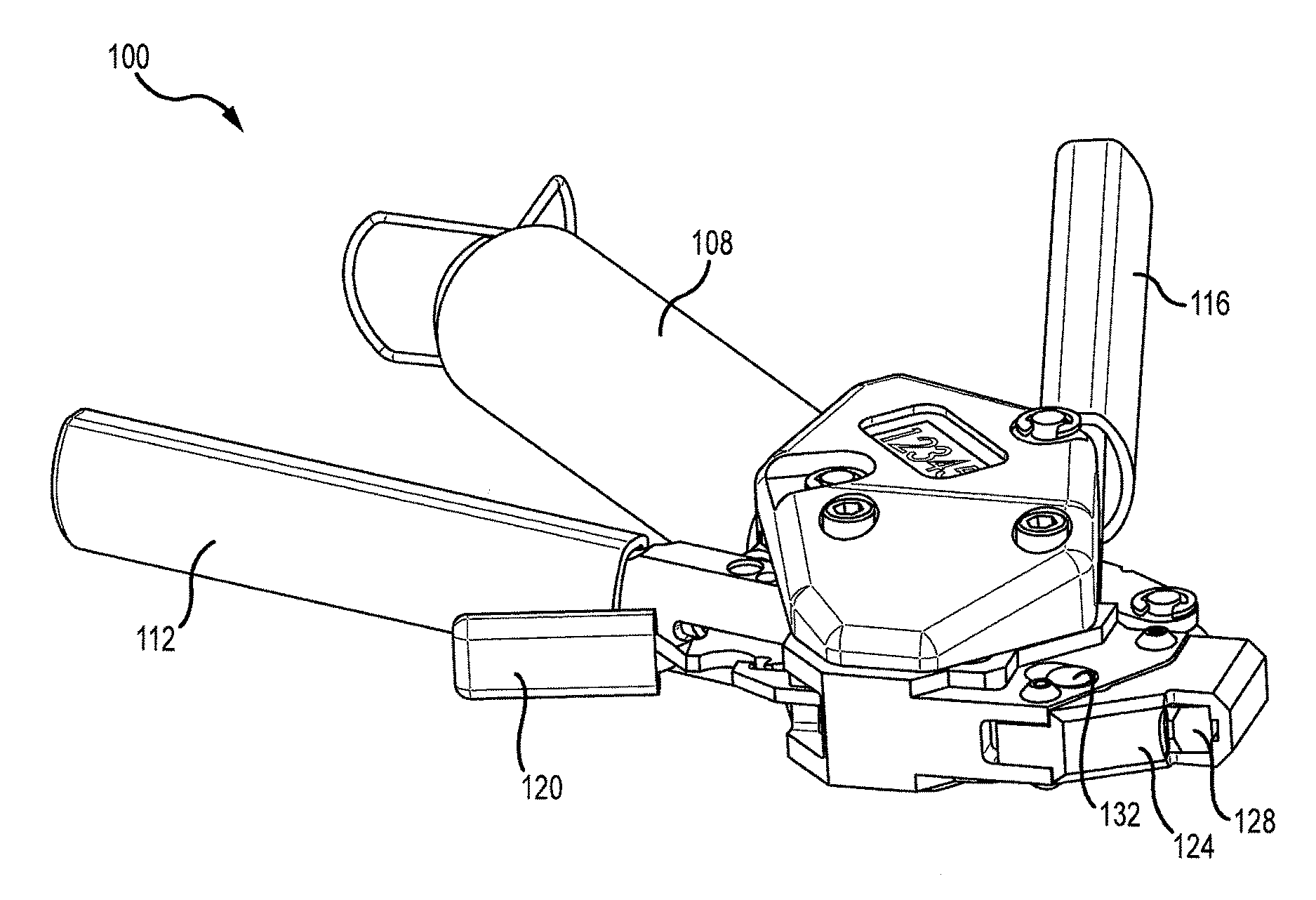
[0050]FIGS. 3-6 show a banding tool 100 of embodiments of the present invention that is designed to tension and secure a band clamp comprising a band and a band locking head. The banding tool 100 includes a head 104 interconnected to a handle 108. A tension handle 112 and a cutoff handle 116 are rotatably interconnected to the head 104 and move relative to the handle 112. A hook 120 is also rotatably interconnected to the head 104 and is adapted to fix the tension of a band inserted into the head 104. The head 104 also accommodates a blade 124 that is operatively associated with a knife128. As in the existing banding tools, a front gripper 132 is used to tension the band by operation of the tension handle 112. The operation of this embodiment of the present invention is a very similar to that shown and described in U.S. Pat. No. 5,566,726 mentioned above.

[0051]FIGS. 7 and 8 show the inner workings of one embodiment of the present invention. The handle 108 includes a spring 136 that ...


PUM


Abstract

A method and apparatus for securing a cable tie about an object is described. Further, a relatively compact banding tool that facilitates cable tie tensioning is described.

Description

[0001]This application is a Continuation-In-Part of U.S. patent application Ser. No. 14 / 685,330, filed Apr. 13, 2015, which claims the benefit of U.S. Provisional Patent Application Ser. No. 61 / 990,339, filed May 8, 2014, the entirety of which is incorporated by reference herein.[0002]This application also claims the benefit of U.S. Provisional Patent Application Ser. No. 62 / 239,635, filed Oct. 9, 2015, the entirety of which is incorporated by reference herein.[0003]This application is related to U.S. Pat. Nos. 5,566,726 and 4,896,402, the entire disclosures of which are incorporated by reference herein.[0004]This application is also related to U.S. Patent Application Publication No. 2013 / 0199382, the entirety of which is incorporated by reference herein.FIELD OF THE INVENTION[0005]Embodiments of the present invention relate to a method and apparatus for securing a cable tie about an object, and in particular, to a relatively compact banding tool that facilitates cable tie tensionin...

Claims


Application Information

Patent Timeline
Patent Type & Authority Applications(United States)
IPC IPC(8): B65B13/02B65B13/34
CPCB65B13/345B65B13/027B26D1/045B26D5/10B26D5/14B26D2001/0066B26D2007/0093
Inventor MARELIN, MIKLOS B.
Owner BAND IT IDEX
Learn More