Signal selecting device

a signal selection and signal technology, applied in the direction of resonators, electrical equipment, waveguides, etc., can solve the problems of increasing the number of components and the circuit area, and achieve the effect of adjusting the bandwidth, facilitating design, and reducing the number of components

Inactive Publication Date: 2009-03-12
NTT DOCOMO INC
View PDF9 Cites 5 Cited by
  • Summary
  • Abstract
  • Description
  • Claims
  • Application Information

AI Technical Summary

Benefits of technology

[0007]According to the present invention, the resonating parts having the ring conductor and the switches can arbitrarily change the susceptance slope parameter highly independently of the resonant frequency. Therefore, the signal selecting device can be easily designed to have desired characteristics. In addition, the bandwidth and the in-band and out-band characteristics can also be changed by changing the susceptance slope parameter of the resonating parts.
[0008]Furthermore, in a case where the resonating parts have variable reactance means connected to the ring conductor at appropriate interva...

Problems solved by technology

Related arts, such as that disclosed in the non-patent literature 1, have a problem that, as the number of comb...

Method used


Image

  • Signal selecting device
  • Signal selecting device
  • Signal selecting device

Examples


embodiment 1

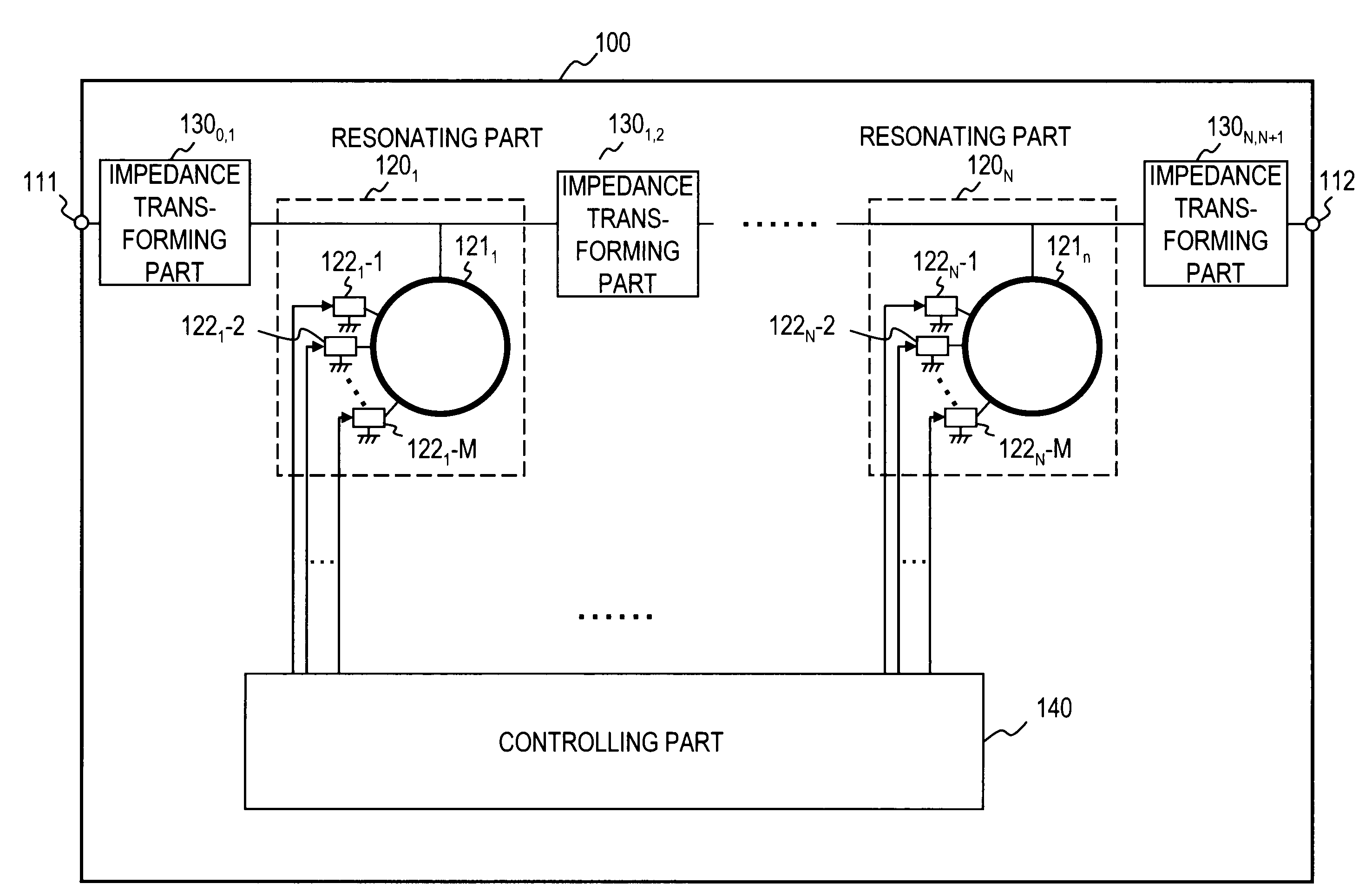
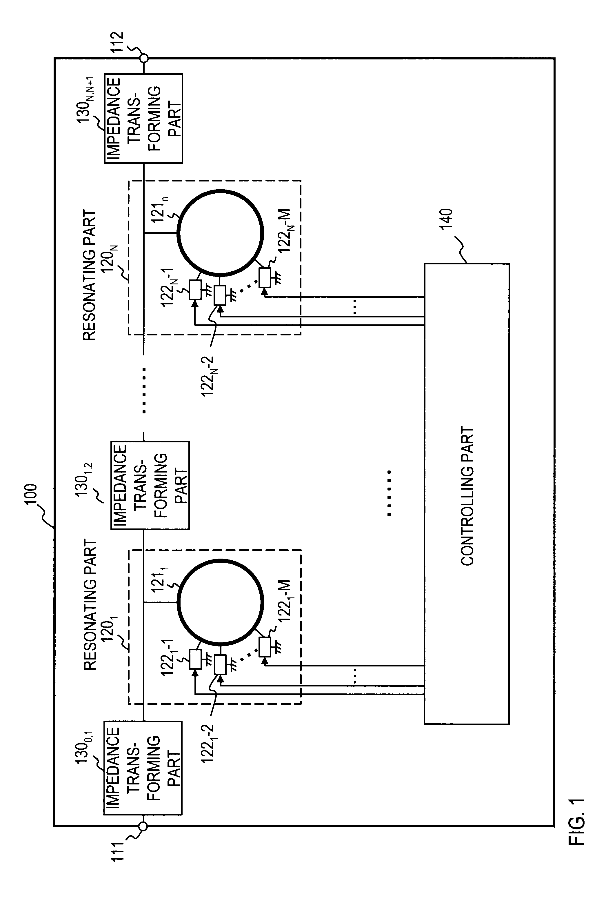
[0048]FIG. 1 is a diagram showing an exemplary functional configuration of a signal selecting device according to an embodiment 1. A signal selecting device 100 has two input / output ports 111 and 112, N resonating parts 1201 to 120N, N+1 impedance transforming parts 1300,1 to 130N,N+1, and a controlling part 140. The resonating part 120n (n represents any integer in a possible range and is an integer from 1 to N in this case) has a ring conductor 121n having a length equal to one wavelength at a resonant frequency or an integral multiple thereof, and M switches 122n-1 to 122n-M each of which is connected to a different part of the ring conductor 121n at one end thereof and to a ground conductor at the other end thereof. The controlling part 140 controls the state of the N*M switches 1221-1 to 122N-M. (“N*M” shows multiplying N by M.) The resonating parts 1201 to 120N are disposed in series between the two input / output ports. The impedance transforming parts 1300,1 to 130N,N+1 are di...

embodiment 2

[0059]In the embodiment 1, a signal selecting device according to the present invention has been generally described. In an embodiment 2, a signal selecting device according to the present invention will be specifically described. FIG. 6 is a diagram showing an exemplary functional configuration of a signal selecting device according to the embodiment 2. A signal selecting device 200 has input / output ports 211 and 212, three resonating parts 2201 to 2203, four impedance transforming parts 2300,1 to 2303,4, and a controlling part 240. The resonating part 220n has a ring conductor 221n. Although not shown in FIG. 6, the resonating part 220n has switches as in the embodiment 1. The input / output ports 211 and 212 have a port impedance of 50Ω. The resonating part 220n has a resonant frequency of 5 GHz, and the ring conductor 221n has a characteristic impedance of 50Ω. For the convenience of explanation, it is assumed that the position of grounding of the resonator is changed instead of s...

embodiment 3

[0064]In the embodiment 2, all the impedance transforming parts have the same, fixed characteristics. If such identical impedance transforming parts are used in this way, the signal selecting device can be easily designed and fabricated. However, the impedance transforming parts do not always have to have the same characteristics but can have different characteristics or variable characteristics. FIG. 8 is a diagram showing an exemplary functional configuration of a signal selecting device according to an embodiment 3. A signal selecting device 300 has two input / output ports 311 and 312, N resonating parts 3201 to 320N, N+1 impedance transforming parts 3300,1 to 230N,N+1 capable of changing the characteristics, and a controlling part 340. While all the impedance transforming parts 3300,1 to 330N,N+11 are shown as being capable of changing the characteristics in FIG. 8, only one particular impedance transforming part may be capable of changing the characteristics. The resonating part...


PUM


Abstract

A signal selecting device according to the present invention has two input/output ports, a plurality of resonating parts, a plurality of impedance transforming parts, and a controlling part. The resonating parts have a ring conductor having a length equal to one wavelength at a resonant frequency or an integral multiple thereof and a plurality of switches each of which is connected to a different part of the ring conductor at one end and to a ground conductor at the other end. The controlling part controls the state of the switches. The resonating parts are disposed in series between the two input/output ports. The impedance transforming parts are disposed between the input/output ports in such a manner that the impedance transforming parts at the both ends are disposed between the input/output port and the resonating part and the remaining impedance transforming parts are disposed between the resonating parts.

Description

BACKGROUND OF THE INVENTION[0001]The present invention relates to a signal selecting device used in transmission, reception or transmission / reception of information. In the field of radio communication using radio waves, necessary signals and unnecessary signal are separated by extracting signals at a particular frequency from a large number of signals. Filters that perform this function comprise a resonator and an impedance transforming circuit and are incorporated in many radio devices. Such filters cannot change design parameters, such as the center frequency and the bandwidth. Therefore, a radio communication device using a plurality of combinations of center frequencies and bandwidths has to have a number of filters equal to the number of combinations of center frequencies and bandwidths and select a filter for use by means of a switch or the like. For example, a non-patent literature 1 (DoCoMo Technical Journal Vol. 14, No. 2, pp. 31-37) discloses a related art in which a filt...

Claims


Application Information

Patent Timeline
IPC IPC(8): H01P1/10
CPCH01P1/20381H01P7/088H01P1/2039
Inventor KAWAI, KUNIHIROSATOH, KEIOKAZAKI, HIROSHINARAHASHI, SHOICHI
Owner NTT DOCOMO INC
Why Eureka
Try Eureka