Tensioning device and tensioning method for steel wire rope of cage guide of ultra-deep vertical shaft

a technology of cage guide and tensioner, which is applied in the direction of earth-moving drilling, mining structures, and elevators, etc., can solve the problems of shaft guide rope tensioning, small counterweight size, and production delay, so as to reduce space occupation, save space cost, and reduce the requirement for hydraulic systems

Active Publication Date: 2017-01-19
CHINA UNIV OF MINING & TECH
View PDF5 Cites 5 Cited by
  • Summary
  • Abstract
  • Description
  • Claims
  • Application Information

AI Technical Summary

Benefits of technology

The present invention is a tensioning apparatus for steel wire rope used in oil and gas wells. It uses a down-hole arrangement for the steel-rope guide and a combined tensioning method that incorporates counterweight tensioning and hydraulic tensioning. This reduces space occupation and the requirement for a hydraulic system, saving space and cost. The tensioning force on the steel wire rope can be effectively monitored, controlled, and adjusted. The apparatus has a simple structure, reliable performance, and low cost, and achieves automatic rope regulation, low cost, and high practicability.

Problems solved by technology

The technical problem addressed in this patent text relates to finding better ways to tension shaft guide ropes in hoists in coa mines without experiencing issues like difficulty in installation or maintaining proper tensioning force. Existing methods like counterweight tensioning and hydraulic tensioning face limitations including requiring larger equipment sizes and higher costs, which make them unappealing options for use in current and future operations.

Method used


Image

  • Tensioning device and tensioning method for steel wire rope of cage guide of ultra-deep vertical shaft
  • Tensioning device and tensioning method for steel wire rope of cage guide of ultra-deep vertical shaft
  • Tensioning device and tensioning method for steel wire rope of cage guide of ultra-deep vertical shaft

Examples


Embodiment Construction

[0020]Hereunder the present invention will be further detailed, with reference to the accompanying drawings.

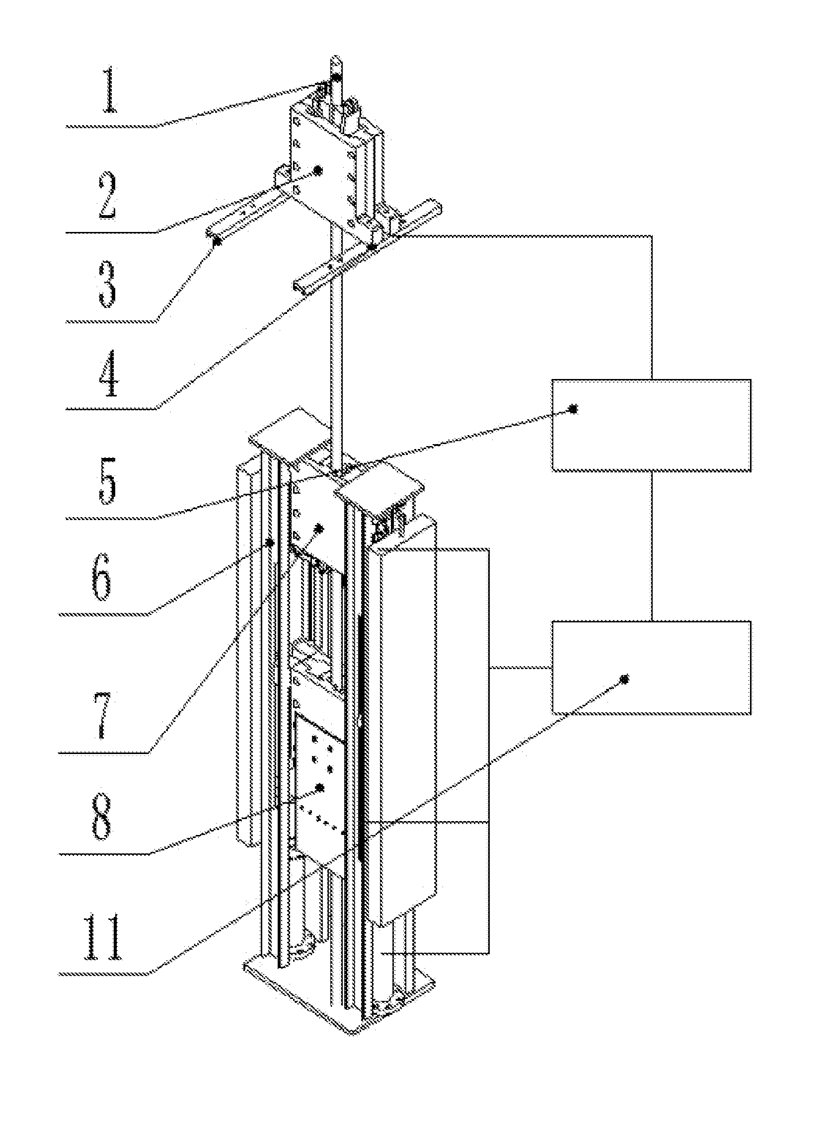
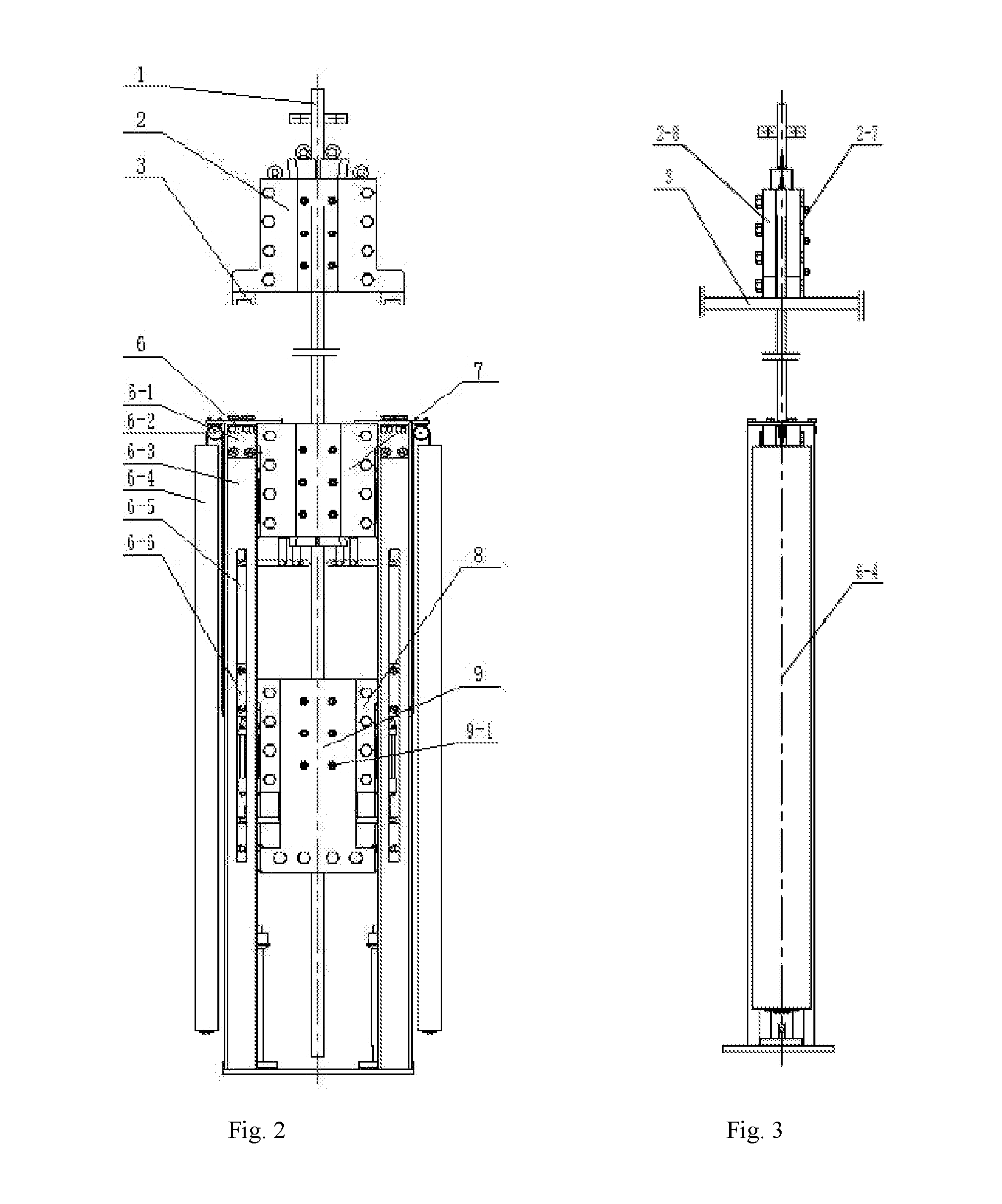
[0021]As shown in FIGS. 1-4, the present invention provides an ultra-deep shaft guide steel wire rope tensioner, comprising an upper rope clamping device 2, a rope adjusting guide frame 6, a lower hydraulic rope locking device 7, and lower hydraulic rope adjusting device 8.

[0022]The upper rope clamping device 2 is fixed to a hoisting sheave headframe 3 by a set of symmetric bolts 2-5, a rope clamp 2-1 is mounted on the upper part of the upper rope clamping device 2, a pressure sensor 4 is arranged at the bottom of the upper rope clamping device 2, and the pressure sensor 4 is connected to a control console 4 via a wireless signal emission module, to transmit pressure signals to the control console 5. The rope adjusting guide frame 6 comprises a steel frame body 6-3, a fixed double clamp plate 6-1 is welded on the upper part of the steel frame body 6-3, an upper guide sheave 6-...


PUM

PropertyMeasurementUnit
Fractionaaaaaaaaaa
Fractionaaaaaaaaaa
Forceaaaaaaaaaa

Abstract

A tensioning device and a tensioning method for a steel wire rope of a cage guide of an ultra-deep vertical shaft. The tensioning device comprises an upper rope clamping device, a rope adjustment guide frame, a lower hydraulic rope locking device, and a lower hydraulic rope adjustment device. The upper rope clamping device is provided with a rope clamp and a pressure sensor. The rope adjustment guide frame comprises a steel frame body, double fixed clamp-plates, a balance weight, and a balance weight steel wire rope. Double moving clamp-plates are disposed in a guide groove of the steel frame body. The double moving clamp-plates are provided with a rope clamp and a lower guide pulley. The double fixed clamp-plates are provided with an upper guide pulley. The balance weight is provided with a fastening joint. Each of the upper rope clamping device, the lower hydraulic rope locking device and the lower hydraulic rope adjustment device comprises a wedged iron block and a shim. Each of the lower hydraulic rope locking device and the lower hydraulic rope adjustment device further comprises a lever wedge adjustment mechanism and a wedge adjustment hydraulic cylinder. A wedge adjustment hydraulic pressing rod is connected to the wedged iron block. The bodies of the wedge adjustment hydraulic cylinders are connected to the shims. The tensioning device and the tensioning method can be used for implementing automatic adjustment and control of the tensile force of the steel wire rope of the cage guide of the ultra-deep vertical shaft.

Description


Claims


Application Information

Patent Timeline
Owner CHINA UNIV OF MINING & TECH
Why Eureka
Try Eureka