Check patentability & draft patents in minutes with Patsnap Eureka AI!

Anchor having a controlled driver orientation

a driver orientation and control technology, applied in the field of medical equipment and procedures for reconstructing ligaments, can solve the problems of limiting the surface area contact established between the graft ligament and the side wall, tearing or rupture of ligaments, and limiting the region

Inactive Publication Date: 2017-01-26
SMITH & NEPHEW INC
View PDF4 Cites 11 Cited by
  • Summary
  • Abstract
  • Description
  • Claims
  • Application Information

AI Technical Summary

Benefits of technology

The new screw design enhances bone-to-ligament integration by reducing bulk within the bone tunnel, facilitating complete absorption and improving the strength of the graft-ligament junction.

Problems solved by technology

In many cases, ligaments are torn or ruptured as the result of an accident.
However, the interference screw itself generally takes up a substantial amount of space within the bone tunnel, which can limit the surface area contact established between the graft ligament and the side wall of the bone tunnel.
This in turn limits the region of bone-to-ligament in-growth, and hence can affect the strength of the joinder.
However, these absorbable interference screws still suffer from several disadvantages.
Second, clinical evidence suggests that absorption generally takes a substantial period of time, e.g., on the order of three years or so.
Thus, during this absorption time, the bone-to-ligament in-growth is still significantly limited by the presence of the interference screw.
Third, clinical evidence suggests that, for many patients, absorption is never complete, leaving a substantial foreign mass remaining within the body.

Method used


Image

  • Anchor having a controlled driver orientation
  • Anchor having a controlled driver orientation
  • Anchor having a controlled driver orientation

Examples


Embodiment Construction

[0056]The following description of the preferred embodiment(s) is merely exemplary in nature and is in no way intended to limit the disclosure, its application, or uses.

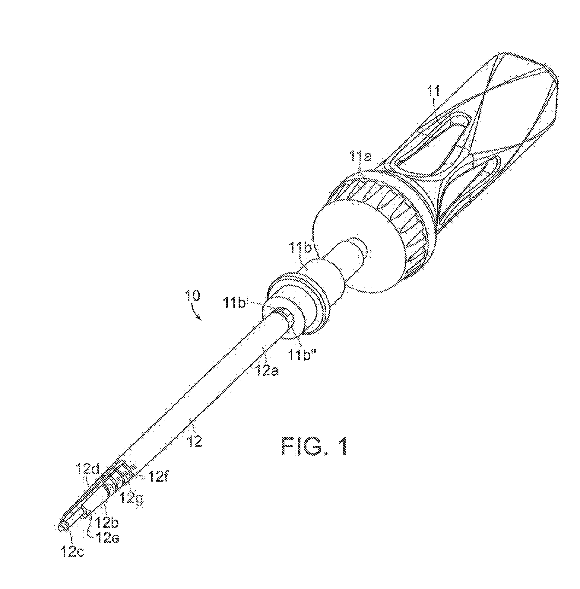
[0057]FIG. 1 shows a first embodiment of the delivery device 10 of the present disclosure. The device 10 includes a handle assembly 11 and a shaft 12 coupled to the handle assembly 11. The handle assembly 11 includes a handle 11a and a connector 11b coupled to the handle 11a. The connector 11b has a channel 11b′ and an opening 11b″ to the channel 11b′. The opening 11b″ is in the shape of a “D”. A proximal end 12a of the shaft 12 is disposed within the channel 11b′.

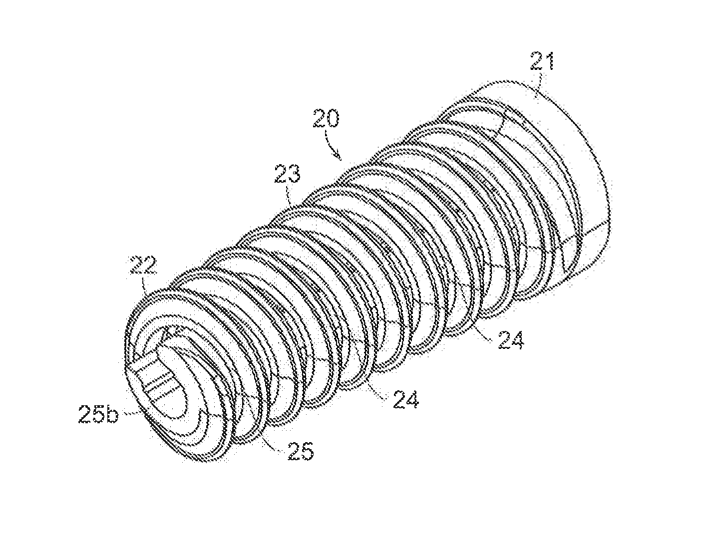
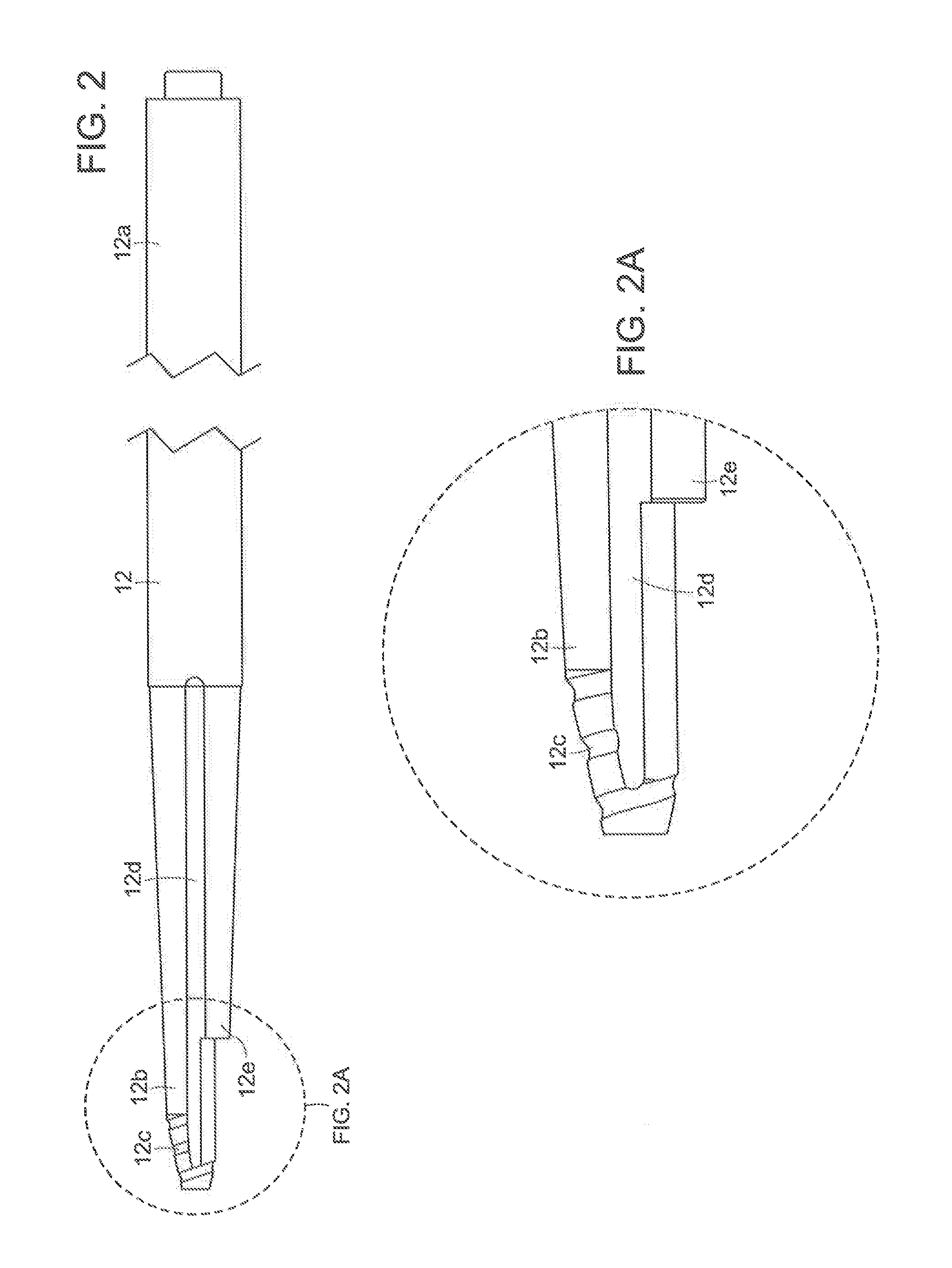
[0058]FIGS. 2, 2A, and 3-4 show the shaft 12. The shaft 12 includes a proximal end 12a and a distal end 12b. The proximal end 12a is in the shape of a “D” to match the shape of the opening 11b″. The distal end 12b includes threads 12c, grooves 12d, and a depth stop 12e. The grooves 12d extend a partial length of the shaft 12 and intersect the threads 12c. ...


PUM


Abstract

The present disclosure relates to an interference screw having a body with a proximal end, distal end, and longitudinal axis extending between thereinbetween. The screw further includes threads for fixing the screw into bone. The screw further includes a through bore defined by the body. The through bore extends between the proximal and distal ends along the longitudinal axis, and has a surface. The screw further includes a controlling member formed by the through bore surface. To install the screw into bone, a surgeon turns the screw with a driver that engages with the controlling member. The driver only engages the controlling member when it is in a driving orientation with respect to the controlling member. Advantageously, with this “one-way” engagement the surgeon can control and confirm the orientation of the driver without seeing the driver and / or screw.

Description

CROSS-REFERENCE TO RELATED APPLICATIONS[0001]This application is a continuation of co-pending U.S. patent application Ser. No. 14 / 085,295, filed Nov. 20, 2013, which in turn is a continuation-in-part application of U.S. patent application Ser. No. 13 / 044,777, filed Mar. 10, 2011, now U.S. Pat. No. 8,979,865, which in turn claims priority to U.S. Patent Application Ser. No. 61 / 312,291, filed Mar. 10, 2010, U.S. Patent Application Ser. No. 61 / 334,808, filed May 14, 2010, and U.S. Patent Application Ser. No. 61 / 359,080, filed Jun. 28, 2010 the disclosures of which are incorporated herein by reference in their entireties for all purposes.BACKGROUND[0002]Field of Technology[0003]The present disclosure relates to medical apparatuses and procedures in general, and more particularly to medical apparatuses and procedures for reconstructing a ligament.[0004]Related Art[0005]In many cases, ligaments are torn or ruptured as the result of an accident. Accordingly, various procedures have been de...

Claims


Application Information

Patent Timeline
Patent Type & Authority Applications(United States)
IPC IPC(8): A61B17/86A61B17/88
CPCA61B17/8645A61B17/864A61B17/869A61B2017/00893A61B2017/8655A61B2017/00004A61B2017/00933A61B17/8888A61F2/0811A61B17/0401A61B17/888A61B2017/00455A61B2017/00477A61B2017/00964A61B2017/0409A61B2017/044A61B2017/0458A61F2/0805A61F2002/0841A61F2002/0858A61F2002/0888A61F2250/0097
Inventor BOWMAN, STEVEN MARKBERUBE, ALFRED R.BOURQUE, BERNARD JOSEPHYANG, WEIHOUSMAN, MARK EDWINSTRONCEK, JOHN
Owner SMITH & NEPHEW INC
Features
  • R&D
  • Intellectual Property
  • Life Sciences
  • Materials
  • Tech Scout
  • Unparalleled Data Quality
  • Higher Quality Content
  • 60% Fewer Hallucinations
Learn More