Method and system for interfacing a ceramic matrix composite component to a metallic component

a ceramic matrix composite and metallic technology, applied in the direction of blade accessories, engine fuctions, machines/engines, etc., can solve the problems of shortened life of the segment and shortened life of the nozzl

Active Publication Date: 2017-01-26
GENERAL ELECTRIC CO
View PDF8 Cites 50 Cited by
  • Summary
  • Abstract
  • Description
  • Claims
  • Application Information

AI Technical Summary

Benefits of technology

[0006]In another embodiment, a method of transferring load from a ceramic matrix composite (CMC) vane assembly to a metallic vane assembly support member includes providing the CMC vane assembly wherein the vane assembly includes a radially outer end component including a radially outwardly facing surface having one or more radially outwardly extending load transfer features. The vane assembly further includes, a radially inner end component, and an airfoil body extending between the inner and outer end components. The method further includes engaging the radially outer end component to at least one of a plurality of metallic vane assembly support members spaced circumferentially about a gas flow path. The vane assembly support members including one or more load receiving features shaped complementary to the load transfer features. The load transfer feature includes a wedge-shaped cross-section.

Problems solved by technology

Therefore, if a CMC component is restrained and cooled on one surface during operation, stress concentrations can develop leading to a shortened life of the segment.
To date nozzles formed of CMC materials have experienced localized stresses that have exceeded the capabilities of the CMC material, leading to a shortened life of the nozzle.

Method used


Image

  • Method and system for interfacing a ceramic matrix composite component to a metallic component
  • Method and system for interfacing a ceramic matrix composite component to a metallic component
  • Method and system for interfacing a ceramic matrix composite component to a metallic component

Examples


Embodiment Construction

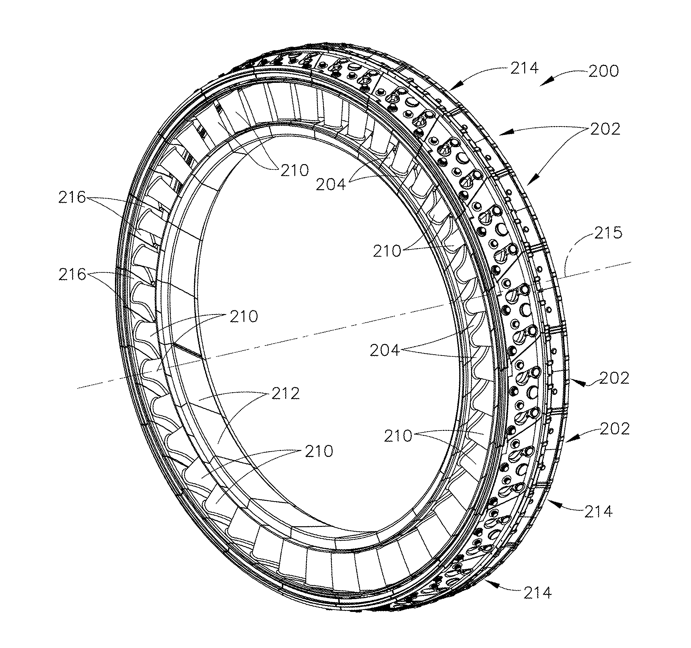
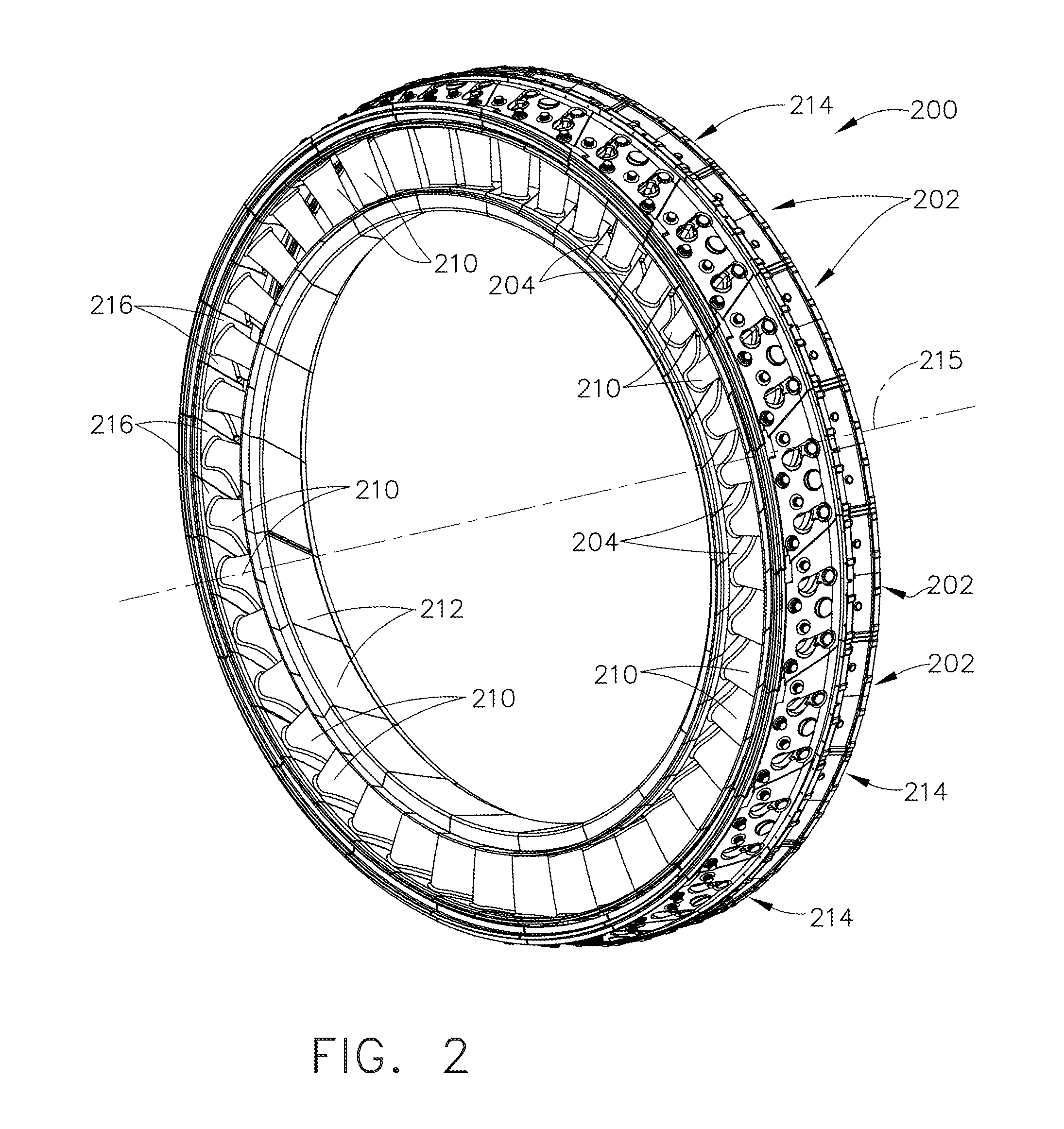
[0027]Embodiments of this disclosure describe nozzle segment assemblies that include an airfoil extending between inner and outer bands that are formed of a composite matrix material (CMC). The CMC material has a temperature coefficient of expansion that is different than the hardware used to support the CMC nozzle segment assemblies. Moreover, the CMC has material properties that tend to limit its ability to withstand forces in certain directions, for example, in a tensile direction or directions in which a tensile component is present, such as, but not limited to twisting or bending directions.

[0028]To interface the CMC nozzle segment assemblies to their respective support structure, which is metallic, new structures are described which permit the CMC nozzle segment assemblies to withstand the high temperature and hostile environment in a gas turbine engine turbine flow path.

[0029]The following detailed description illustrates embodiments of the disclosure by way of example and no...


PUM


Abstract

An airfoil assembly for a gas turbine engine and a method of transferring load from the ceramic matrix composite (CMC) airfoil assembly to a metallic vane assembly support member are provided. The airfoil assembly includes a forward end and an aft end with respect to an axial direction of the gas turbine engine. The airfoil assembly further includes a radially outer end component including a radially outwardly-facing end surface having a non-compression load-bearing feature extending radially outwardly from the outwardly-facing end surface and formed integrally with the outer end component, the feature configured to mate with a complementary feature formed in a radially inner surface of a first airfoil assembly support structure, the feature selectively positioned orthogonally to a force imparted into the airfoil assembly. The airfoil assembly also includes a radially inner end component, and a hollow airfoil body extending therebetween, the airfoil body configured to receive a strut couplable at a first end to the first airfoil assembly support structure.

Description

BACKGROUND[0001]This description relates to a composite nozzle assembly, and, more particularly, to a method and system for interfacing a ceramic matrix composite component to a metallic component in a gas turbine engine.[0002]At least some known gas turbine engines include a core having a high pressure compressor, combustor, and high pressure turbine (HPT) in serial flow relationship. The core engine is operable to generate a primary gas flow. The high pressure turbine includes annular arrays (“rows”) of stationary vanes or nozzles that direct the gases exiting the combustor into rotating blades or buckets. Collectively one row of nozzles and one row of blades make up a “stage”. Typically two or more stages are used in serial flow relationship. These components operate in an extremely high temperature environment, and may be cooled by air flow to ensure adequate service life.[0003]HPT nozzles are often configured as an array of airfoil-shaped vanes extending between annular inner a...

Claims


Application Information

Patent Timeline
Patent Type & Authority Applications(United States)
IPC IPC(8): F01D9/04F01D25/24F01D25/00
CPCF01D9/041F01D25/005F01D25/243F05D2300/6033F05D2240/128F05D2260/30F05D2260/941F05D2220/32F01D9/044F01D5/18F01D5/284F01D9/042
Inventor HEITMAN, BRYCE LORINGSENILE, DARRELL GLENNTUERTSCHER, MICHAEL RAYPHELPS, GREG SCOTTFEIE, BRIAN GREGGMURPHY, STEVEN JAMES
Owner GENERAL ELECTRIC CO
Why Eureka
Try Eureka