
Engine stand with rear mount support

a technology of engine support and rear mount, which is applied in the direction of machine support, packaging goods type, packaged goods, etc., can solve the problems of difficulty in size, shape and weight of engine, require special equipment, and require special training and skill to opera

Inactive Publication Date: 2017-01-26
CATERPILLAR INC
View PDF3 Cites 22 Cited by
  • Summary
  • Abstract
  • Description
  • Claims
  • Application Information

AI Technical Summary

Benefits of technology

The present disclosure includes a stand for an engine and a method of mounting the engine on the stand. The stand includes a base member with a front post and a rear support system with two sleeve members and two rear posts. Each rear post has a clamp for holding a rear mount of the engine. The rear support system is designed to be adjustable at multiple preset positions and can accommodate different diameters of rear mounts. The stand also includes a front post for holding trunnions of different heights. The technical effects of the disclosure include improved stability and flexibility for mounting engines on stands, as well as increased safety and efficiency in the assembly line process.

Problems solved by technology

During shipping, the size, shape and weight of an engine may present a challenge and require specialized equipment.
Such specialized equipment may be expensive to make, require special training and skill to operate, and may increase the time taken for loading and unloading the engine on and off the equipment.

Method used


Image

  • Engine stand with rear mount support
  • Engine stand with rear mount support
  • Engine stand with rear mount support

Examples


Embodiment Construction

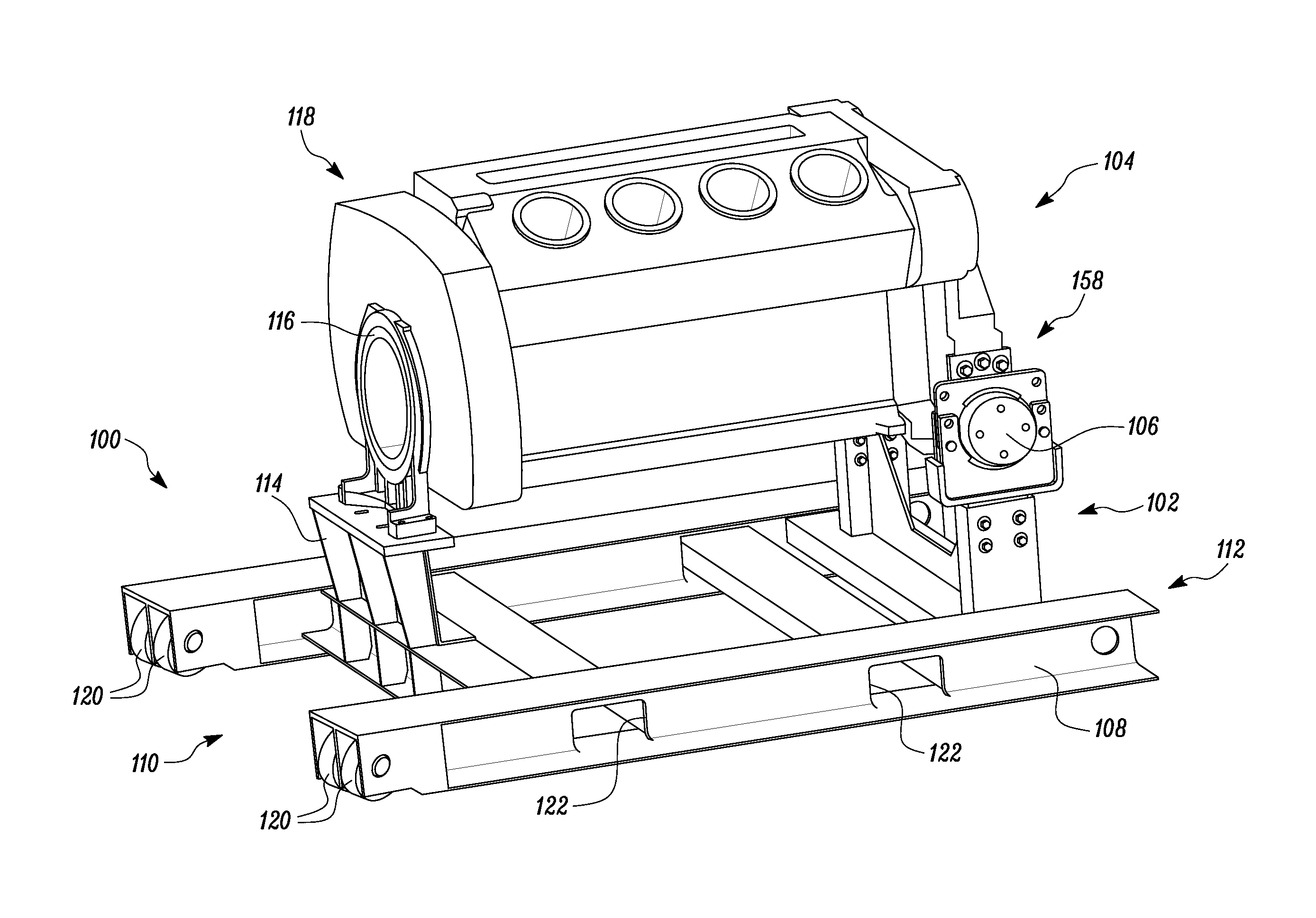
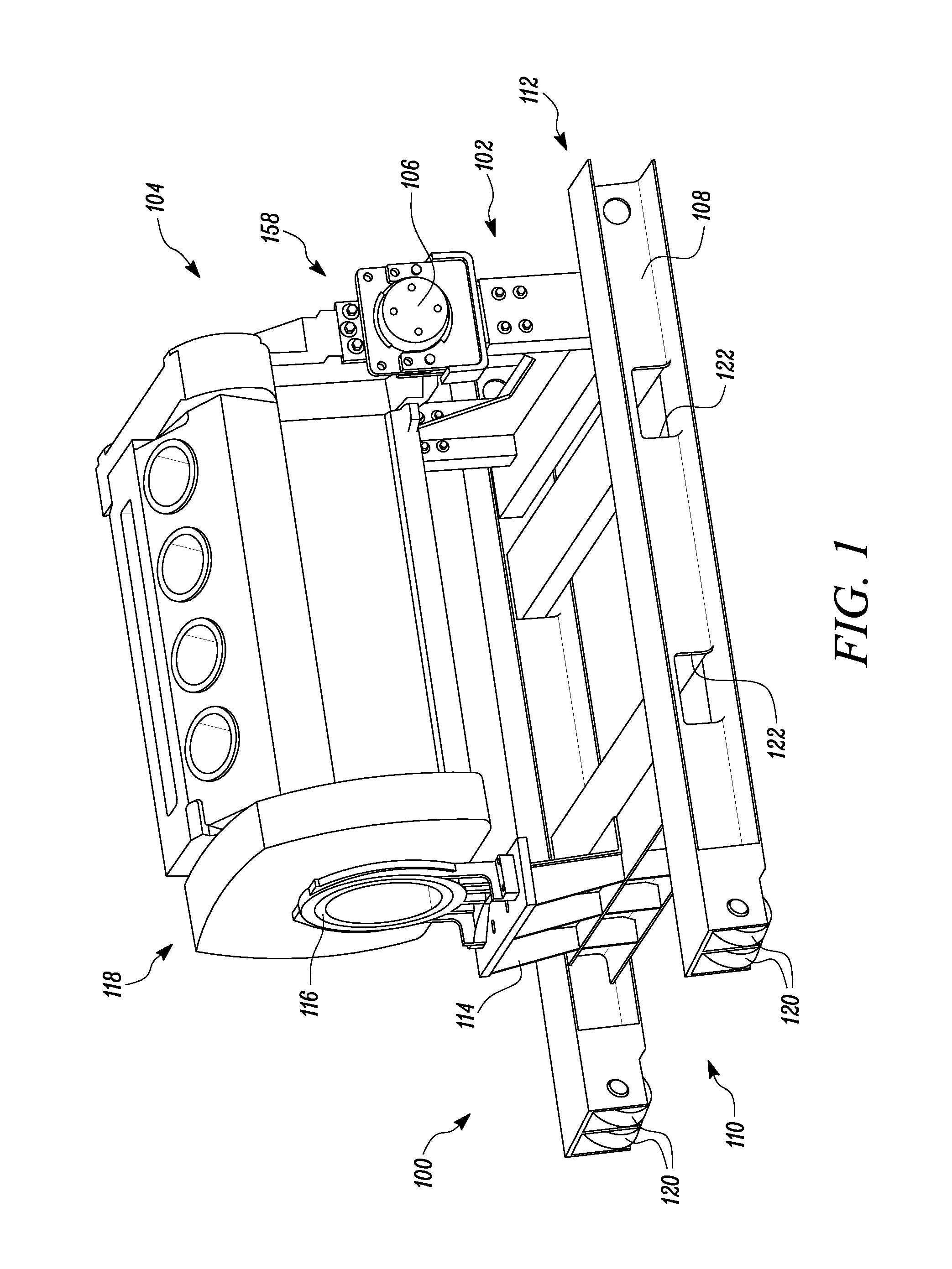
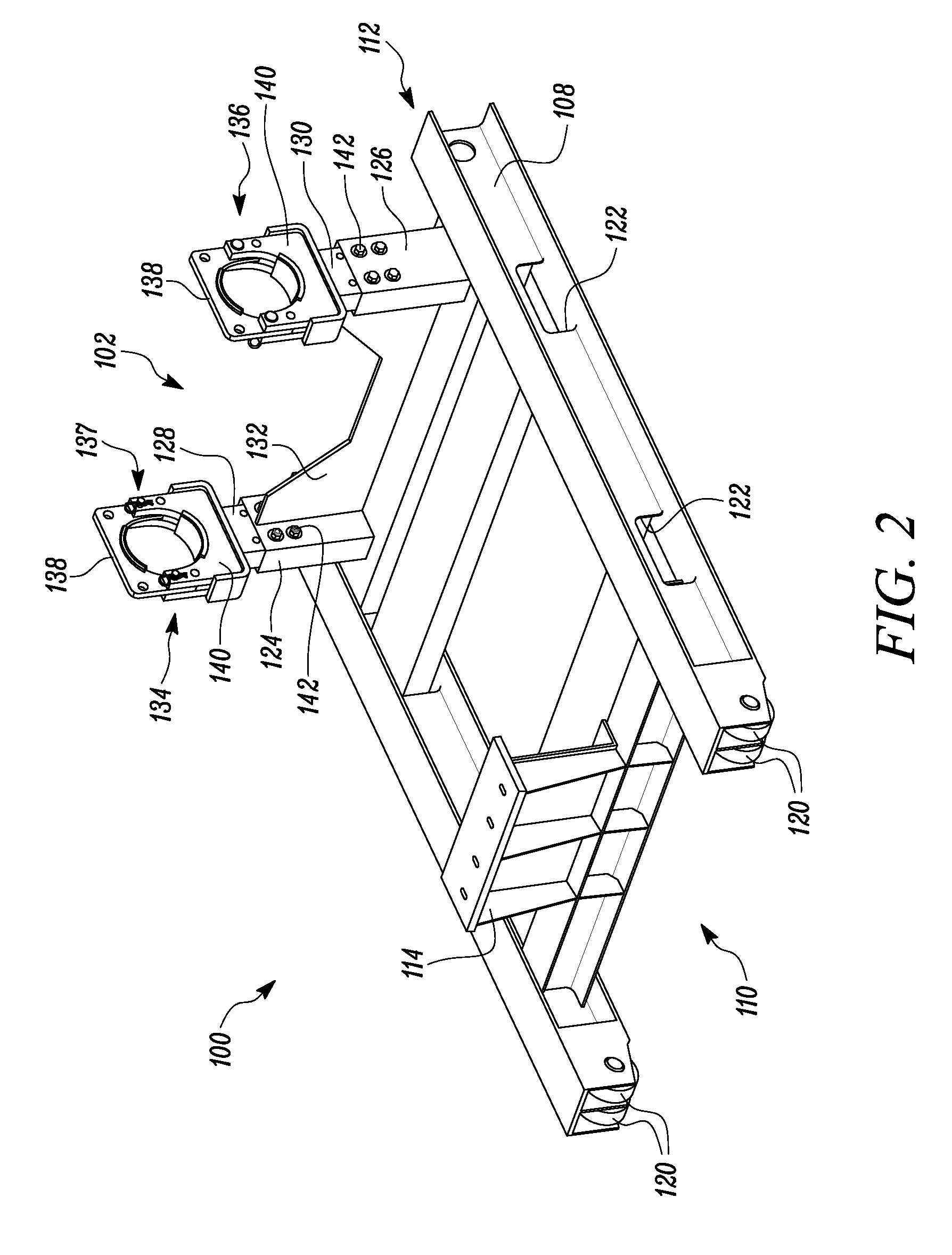
[0014]Wherever possible, the same reference numbers will be used throughout the drawings to refer to the same or the like parts. FIG. 1 illustrates a perspective view of a stand 100 with a rear mount support system 102 depicting an exemplary engine 104 with a rear mount 106 supported on the stand 100, according to one embodiment of the present disclosure. The stand 100 includes a base member 108. The base member 108 includes a first end 110 and a second end 112. The stand 100 further includes a front post 114 fixedly connected to the base member 108 at the first end 110. The base member 108 also includes the rear support system 102 fixedly connected thereto at the second end 112.

[0015]The front post 114 is configured to hold a trunnion 116, which in turn is coupled to a front end 118 of the engine 104. In some embodiments, the front post 114 may be configured to hold trunnions of two different heights. The stand 100 is configured to hold the engine 104 during shipping.

[0016]As shown...


PUM


Abstract

A stand for an engine is provided. The stand includes a base member having a first end and a second end. The base member also includes a front post fixedly connected to the base member at the first end. The base member further includes a rear support system fixedly connected to the base member at the second end. The rear support system includes two sleeve members and two rear posts, such that each rear post is slidably coupled to a sleeve member, and such that each rear post includes a clamp configured to hold a rear mount of the engine.

Description

TECHNICAL FIELD[0001]The present disclosure relates to an engine stand, and more particularly, to an engine stand with rear mount support.BACKGROUND[0002]Engines generally have a variety of sizes, shapes and weights. Engines are generally manufactured separately and need to be shipped to a location where they can be installed into a vehicle. During shipping, the size, shape and weight of an engine may present a challenge and require specialized equipment. Such specialized equipment may be expensive to make, require special training and skill to operate, and may increase the time taken for loading and unloading the engine on and off the equipment. Some engines include a variety of mounts on either front ends or rear ends and require additional support system to be able to remain upright and secure during shipping or transportation. Engines containing different size mounts and at different heights require multiple stands during shipping.[0003]U.S. Pat. No. 4,804,162 describes an engin...

Claims


Application Information

Patent Timeline
IPC IPC(8): F16M11/26B65D61/00F16M11/04
CPCF16M11/26B25H1/0007B65D61/00F16M11/041F16M1/02F16M3/00B65D85/68B65D2585/6877
Inventor KHAN, ZEESHAN
Owner CATERPILLAR INC
Learn More