An optical arrangement and method for imaging a sample

a sample and optical arrangement technology, applied in the field of optical arrangement and imaging methods, can solve the problems of increasing the development cost of the detector, the detector itself can slightly affect the position of the sample, and the detector is quite expensive, so as to save the detector

Active Publication Date: 2017-01-26
EURO LAB FUER MOLEKULARBIOLOGIE EMBL
View PDF3 Cites 5 Cited by
  • Summary
  • Abstract
  • Description
  • Claims
  • Application Information

AI Technical Summary

Benefits of technology

[0015]An optical arrangement for imaging a sample is disclosed. The optical arrangement comprises at least one first objective lens and at least one second objective lens, at least one illumination source for producing an illumination beam, a detector for imaging radiation from the sample, and at least one mirror. The at least one mirror is adapted to reflecting the radiation from one of the first objective lens or the second objective lens into the detector. The position of the mirror is dependent on the illumination beam at the other one of the first objective lens and the second objective lens wherein the mirror can be double-sided. The use of the double-sided mirror enables a single detector to be used to image the sample from multiple sides and thus save on the detectors.

Problems solved by technology

These detectors are quite expensive and a microscope designer will wish to reduce the number of detectors.
The use of a single detector, which is moved during the imaging process, can be disadvantageous in that the movement of the detector itself can slightly effect the position of the sample, due to vibrations.
This movement of the detector requires a precise and fast movement of a part of hardware, which is comparatively massive and in turn leads to further increase in development costs and / or in extra parts of equipment.

Method used


Image

  • An optical arrangement and method for imaging a sample
  • An optical arrangement and method for imaging a sample
  • An optical arrangement and method for imaging a sample

Examples


Embodiment Construction

[0030]The invention will now be described on the basis of the drawings.

[0031]It will be understood that the embodiments and aspects of the invention described herein are only examples and do not limit the protective scope of the claims in any way. The invention is defined by the claims and their equivalents. It will be understood that features of one aspect or embodiment of the invention can be combined with the feature of a different aspect or aspects and / or embodiments of the invention.

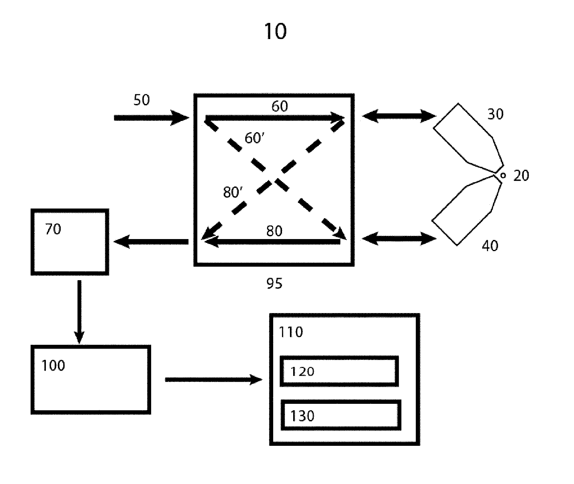
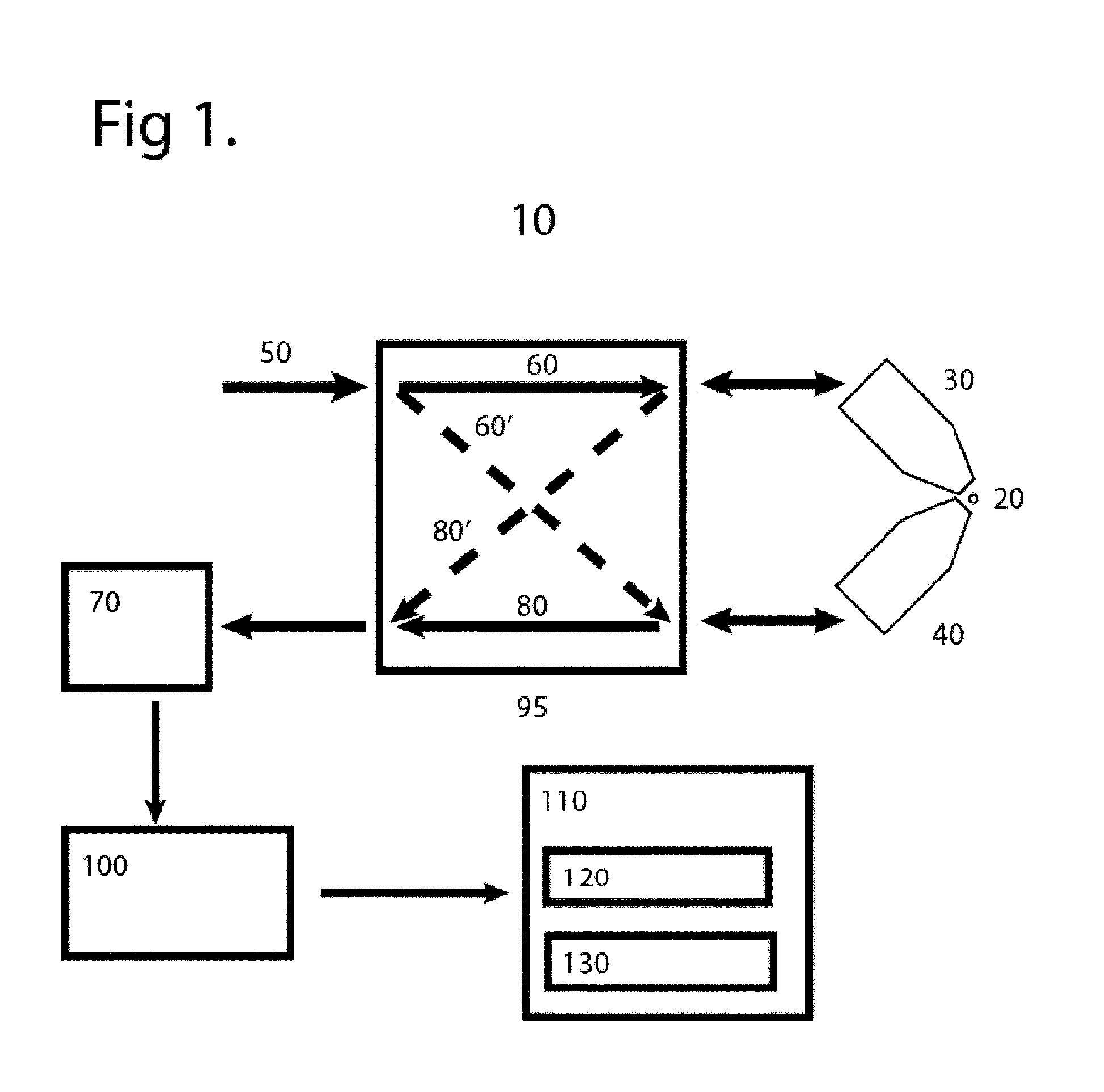
[0032]FIG. 1 shows an overview of an optical arrangement 10 of this disclosure. The optical arrangement 10 has a first objective lens 30 and a second objective lens 40. Both the first objective lens 30 and the second objective lens 40 are able to image a sample 20 and / or direct an illumination beam 60 and 60′ onto the sample 20. The optical arrangement 10 shown in FIG. 1 has two objective lenses 30 and 40, but this is not limiting of the invention. It would be possible to have an optical arrangement...


PUM


Abstract

An optical arrangement for imaging a sample is disclosed. The optical arrangement comprises at least one first objective lens and at least one second objective lens, at least one illumination source for producing an illumination beam, detector for imaging radiation from the sample, and at least one mirror for reflecting the radiation from one of the first objective lens or the second objective lens into the detector. The at least one mirror is double-sided and dependent on the illumination beam at the other one of the first objective lens and the second objective lens.

Description

CROSS-RELATION TO OTHER APPLICATIONS[0001]NoneFIELD OF THE INVENTION[0002]The invention relates to an optical arrangement and a method for imaging a sample using at least two illumination beams.BACKGROUND TO THE INVENTION[0003]A microscope is a scientific instrument that is used for the visualization of objects, which can be either small cells or have details that are too small to be resolved by the naked eye.[0004]There are many types of microscopes available on the market. The most common of these and the first to be invented is the so-called optical microscope, which uses light in a system of lenses to magnify images of the samples. The image from the optical micro-scope can be either viewed through an eyepiece or, more commonly nowadays, captured by a light-sensitive camera sensor to generate a so-called micrograph. There are a wide range of sensors available to catch the images. Non-limiting examples are charge-coupled devices (CCD) and scientific complementary metal-oxide semi...

Claims


Application Information

Patent Timeline
Patent Type & Authority Applications(United States)
IPC IPC(8): G02B21/18G02B21/36G02B21/16G02B21/06
CPCG02B21/18G02B21/06G02B21/361G02B21/16H04N2213/001H04N13/0007H04N13/0207H04N13/0282G02B21/367H04N13/106H04N13/207H04N13/282
Inventor QUINTAS GLASNER DE MEDEIROS, GUSTAVOHUFNAGEL, LARSNORLIN, NILS
Owner EURO LAB FUER MOLEKULARBIOLOGIE EMBL
Why Eureka
Try Eureka