Cooling system

a cooling system and integrated technology, applied in the direction of machines/engines, lighting and heating apparatus, turbine/propulsion fuel heating, etc., can solve the problem of inefficient use of heat exchangers

Active Publication Date: 2017-02-02
GENERAL ELECTRIC CO
View PDF7 Cites 44 Cited by
  • Summary
  • Abstract
  • Description
  • Claims
  • Application Information

AI Technical Summary

Benefits of technology

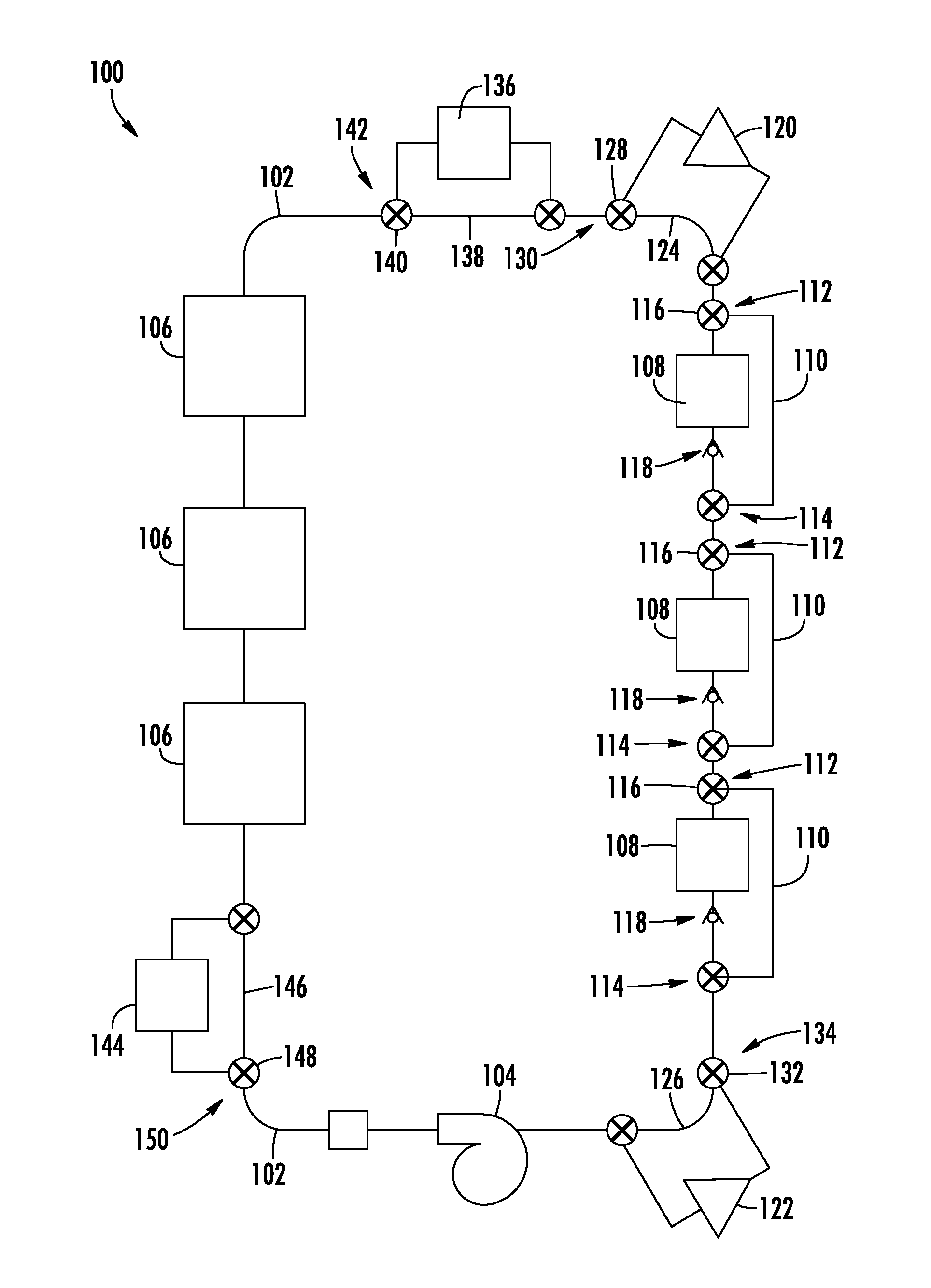
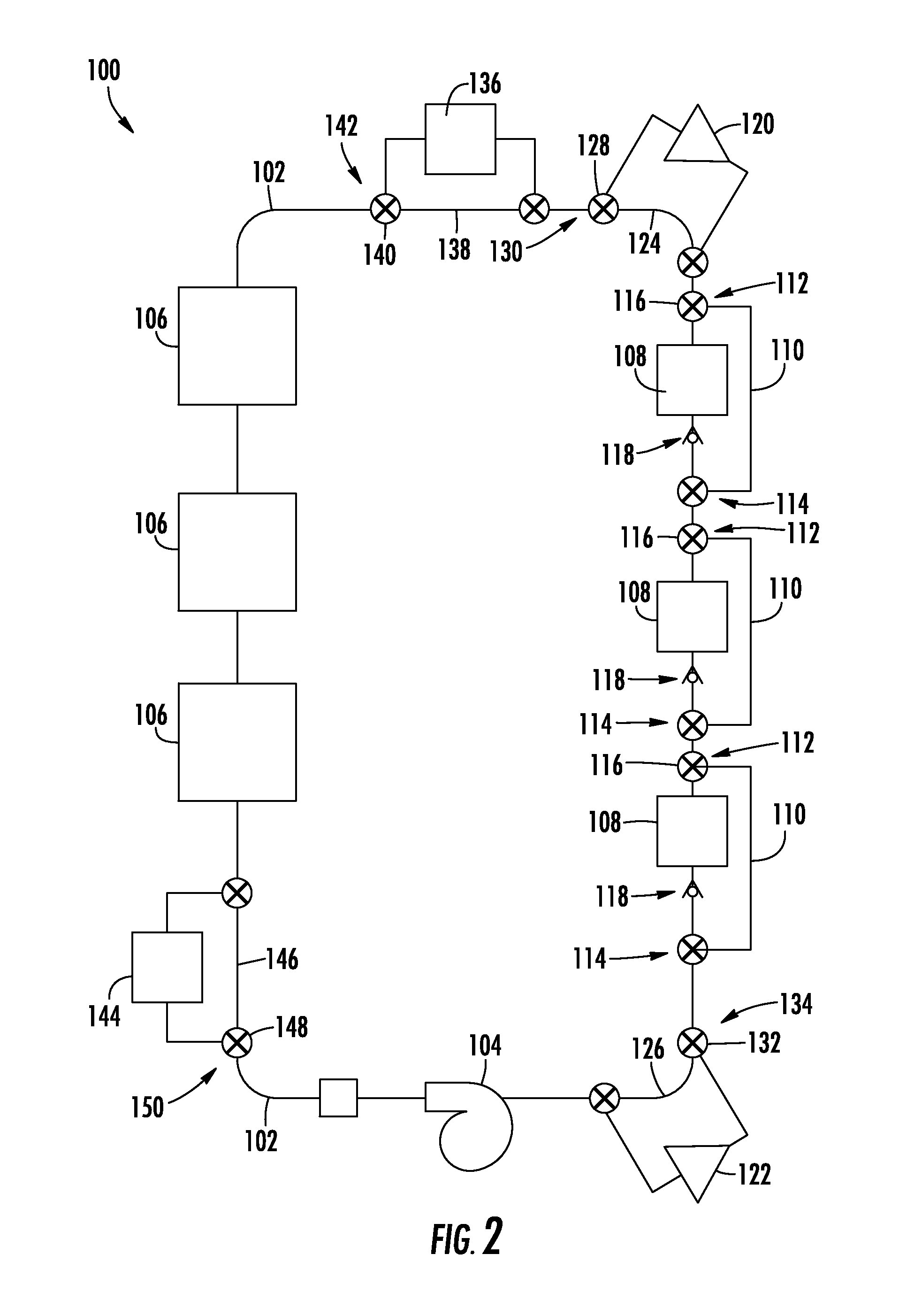
[0008]In another exemplary embodiment of the present disclosure, a gas turbine engine is provided. The gas turbine engine includes a compressor section coupled to a turbine section by one or more shafts and a main lubrication system for providing lubrication to one or more components located in at least one of the compressor section or the turbine section. The gas turbine engine also includes a thermal management system having a thermal transport bus having a heat exchange fluid flowing therethrough and a plurality of heat source exchangers in therma

Problems solved by technology

Such a configuration may result in an

Method used


Image

  • Cooling system
  • Cooling system
  • Cooling system

Examples


Embodiment Construction

[0014]Reference will now be made in detail to present embodiments of the invention, one or more examples of which are illustrated in the accompanying drawings. The detailed description uses numerical and letter designations to refer to features in the drawings. Like or similar designations in the drawings and description have been used to refer to like or similar parts of the invention. As used herein, the terms “first”, “second”, and “third” may be used interchangeably to distinguish one component from another and are not intended to signify location or importance of the individual components. The terms “upstream” and “downstream” refer to the relative direction with respect to fluid flow in a fluid pathway. For example, “upstream” refers to the direction from which the fluid flows, and “downstream” refers to the direction to which the fluid flows.

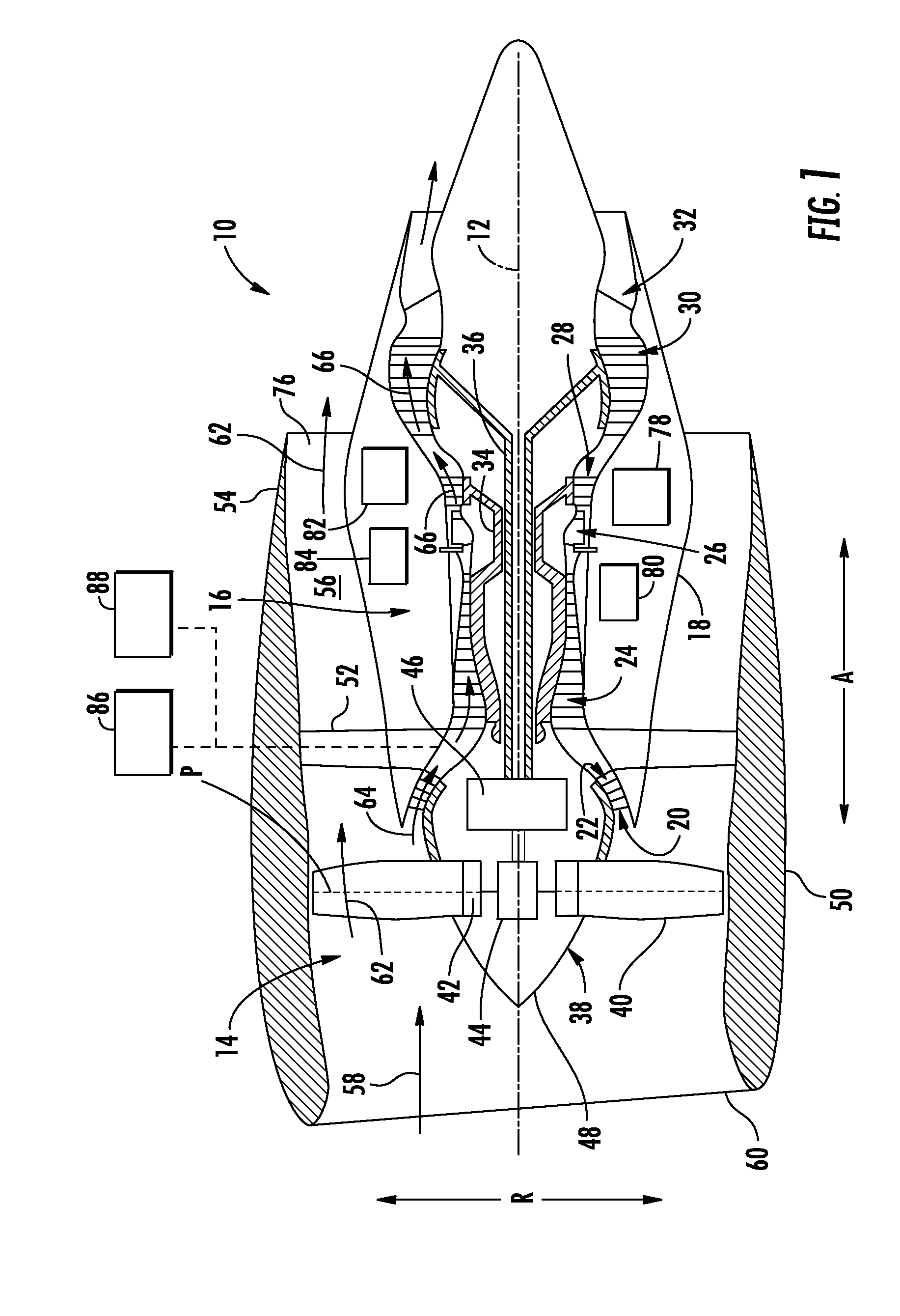
[0015]Referring now to the drawings, wherein identical numerals indicate the same elements throughout the figures, FIG. 1 is a schematic...


PUM


Abstract

A thermal management system for a gas turbine engine and/or an aircraft is provided including a thermal transport bus having a heat exchange fluid flowing therethrough. The thermal management system also includes a plurality of heat source exchangers and at least one heat sink exchanger. The plurality of heat source exchangers and the at least one heat sink exchanger are in thermal communication with the heat exchange fluid in the thermal transport bus. The plurality of heat source exchangers are arranged along the thermal transport bus and configured to transfer heat from one or more accessory systems to the heat exchange fluid, and the at least one heat sink exchanger is located downstream of the plurality of heat source exchangers and configured to remove heat from the heat exchange fluid.

Description

STATEMENT REGARDING FEDERALLY SPONSORED RESEARCH & DEVELOPMENT[0001]The US Government may have certain rights in this invention pursuant to VCAT Phase 1 Technology Development Contract N00014-10-D-0010.FIELD OF THE INVENTION[0002]The present subject matter relates generally to an integrated cooling system for a gas turbine engine and / or an aircraft.BACKGROUND OF THE INVENTION[0003]A gas turbine engine generally includes a fan and a core arranged in flow communication with one another. Various accessory systems are included to ensure that the fan and / or core operate as desired. For example, a main lubrication system provides lubrication to, e.g., bearings and gear meshes within a compressor section, a turbine section, and a power gear box (if provided). In addition to the lubricating properties provided to such components, the main lubrication system removes heat from such components such that they may operate within a desired temperature range.[0004]Other accessory systems of the ga...

Claims


Application Information

Patent Timeline
IPC IPC(8): F02C7/06F02C7/16F25B1/00F25B41/06F28D15/00F28F27/02
CPCF28D15/00F28F27/02F25B1/00F25B41/062F02C7/06F28F2250/08F28D2021/0026F28D2021/0021F02C7/16F02C7/12F02C7/14F02C7/185F02C7/224F05D2260/213Y02T50/60F25B41/31
Inventor CERNY, MATTHEW ROBERTKROGER, CHRISTOPHER JAMESMILLER, BRANDON WAYNE
Owner GENERAL ELECTRIC CO
Why Eureka
Try Eureka