Radiotherapy apparatus

a technology of radiotherapy and apparatus, which is applied in the field of radiotherapy apparatus, can solve the problems of achieve the effect of improving the accuracy of radiation dose delivery and increasing the weight of moving parts

Active Publication Date: 2017-02-09
ELEKTA AB
View PDF2 Cites 6 Cited by
  • Summary
  • Abstract
  • Description
  • Claims
  • Application Information

AI Technical Summary

Benefits of technology

The patent aims to address the issue of reduced accuracy in delivering radiation dosage during medical treatments. Previous methods to address this issue involve stiffening the moving parts, which often results in increased weight. The patent proposes a solution to improve accuracy without increasing the weight of the parts.

Problems solved by technology

Hitherto, this has been seen as a mechanical problem to be solved by stiffening the drum and the gantry arm, but this usually results in an increase in the weight of the moving parts.

Method used


Image

  • Radiotherapy apparatus
  • Radiotherapy apparatus
  • Radiotherapy apparatus

Examples


first embodiment

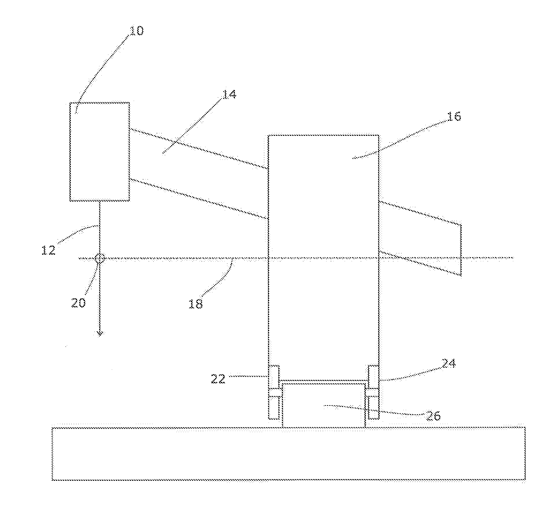
[0024]Thus, one way of correcting for the droop effect, according to the present invention, is to adjust the position of the drum 16 via the wheels 22, 24. An upward adjustment of the front wheels 22, or a downward adjustment of the rear wheels 24, will tend to adjust the isocentre position away from the drum 16, and vice versa (i.e. lowering the front wheels or raising the rear wheels adjusts the isocentre position towards the drum). Thus, this can be used to fine-tune the isocentre position and counteract the influence of gravity.

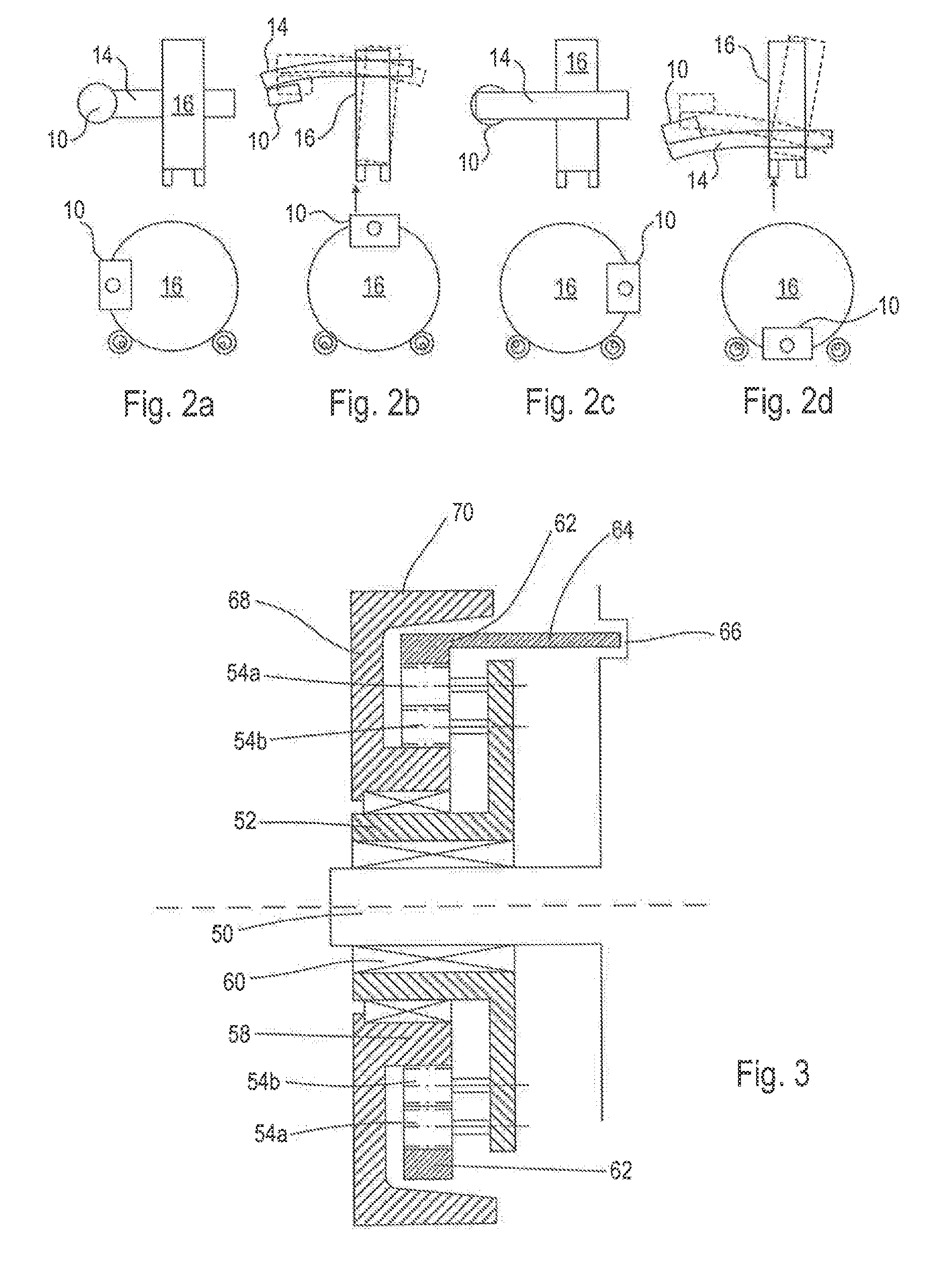
[0025]The heights of the wheels 22, 24 could be adjusted via a cam surface within the wheel mountings, for example, or by any suitable mechanism. Our preferred mechanism is shown in FIGS. 3 and 4 and comprises an epicyclic gear train within the wheel itself. FIG. 3 shows the gear train in section, mounted on a rigid stub axle 50. A planetary gear carrier 52 is mounted eccentrically on the stub axle 50 and carries a set of four planetary gears 54, each spa...

second embodiment

[0033]An alternative solution, according to the present invention, is to adjust the mounting of the gantry arm 14 within the drum 16. As only a very small adjustment is needed, and the load transmitted from the arm to the drum is large, we expect this to be difficult but achievable through the use of levered cam surfaces driven by suitable actuators.

third embodiment

[0034]FIGS. 5 and 6 show a third embodiment in schematic form, illustrated from the front of the apparatus and along the axis of rotation of the drum. Thus, the drum 100 is supported in the manner shown in FIG. 1 by a set of four wheels. Two rear wheels (not shown) support a rear rim 102 of the drum 100, and two front wheels 104, 106 support a front rim 108 of the drum 100. A radiation source 110 is mounted on the drum via a gantry and emits a beam 112 towards the rotation axis of the drum 100.

[0035]The drum thus carries the two rims via which it is supported, the rear rim 102 and the front rim 108. These will usually be defined by a suitable rigid bearing surface along which the wheels 104, 106 etc roll. The rear rim 102 is (in this embodiment) circular, centred on the rotation axis of the drum 100 and thus rotationally symmetric around that axis. However, the front rim 108 is slightly non-circular, having a smooth indentation 140 compared to the circular rear rim 102 (shown in dot...


PUM


Abstract

A radiotherapy apparatus includes a rotatable drum on which is mounted a gantry arm carrying a radiation source. The arm extending from the drum to a location of the radiation source is offset from the axis of rotation of the drum and oriented towards the axis. The radiotherapy apparatus further includes a mechanism configured to apply a tilt to the arm at one or more rotational orientations of the drum. The rotatable drum is supported on wheels beneath the drum, and the mechanism is an eccentric mechanism within the wheels and is configured to apply the tilt to the arm via the wheels.

Description

CROSS REFERENCE TO RELATED APPLICATION[0001]This is a continuation of U.S. application Ser. No. 14 / 524,605, filed Oct. 27, 2014, which claims the benefits of priority to GB 1318983.2, filed on Oct. 28, 2013. Both applications are incorporated herein by reference in their entireties.FIELD OF THE INVENTION[0002]The present invention relates to radiotherapy apparatus.BACKGROUND ART[0003]Many designs of radiotherapy apparatus employ a radiation source mounted on a gantry arm that is rotatable around a patient support on which a patient can be placed for treatment. The usual geometry for this is to provide a circular-section rotatable drum oriented in a vertical plane, i.e. with its axis of symmetry and rotation in a horizontal plane, and mount the gantry arm onto the drum, offset from the axis. The source is then mounted at the end of the gantry arm, oriented so that the beam that it produces is directed towards the axis. The point at which the centre of the beam meets the axis is known...

Claims


Application Information

Patent Timeline
Patent Type & Authority Applications(United States)
IPC IPC(8): A61N5/10A61N5/01
CPCA61N5/01A61N5/1081A61N2005/1057
Inventor BERGFJORD, PER HARALDGNOATO, FRANCESCO
Owner ELEKTA AB
Why Eureka
Try Eureka