Network system, communication analysis method and analysis apparatus

a network system and communication analysis technology, applied in the field of network system, classification method, and apparatus, can solve the problems of difficult classification of communication flow, inability to accurately determine whether, and inability to classify communication flow with unknown feature amoun

Inactive Publication Date: 2017-02-09
HITACHI LTD
View PDF3 Cites 9 Cited by
  • Summary
  • Abstract
  • Description
  • Claims
  • Application Information

AI Technical Summary

Problems solved by technology

That is, it is difficult to classify the communication flow so as to achieve consistent communication control.
Furthermore, in the conventional configuration, communication flows are classified using preset thresholds only, and therefore, it was not possible to classify a communication flow that has an unknown feature amount.
In this case, the classification results of the communications keep changing, and therefore, it is not possible to accurately determine whether or not it is necessary to apply a communication service for improving communication quality such as a WAN accelerator.

Method used


Image

  • Network system, communication analysis method and analysis apparatus
  • Network system, communication analysis method and analysis apparatus
  • Network system, communication analysis method and analysis apparatus

Examples


first embodiment

[0031]In first embodiment, the basic system configuration of the present invention will be explained. Modification examples or specific examples will be explained in other embodiments.

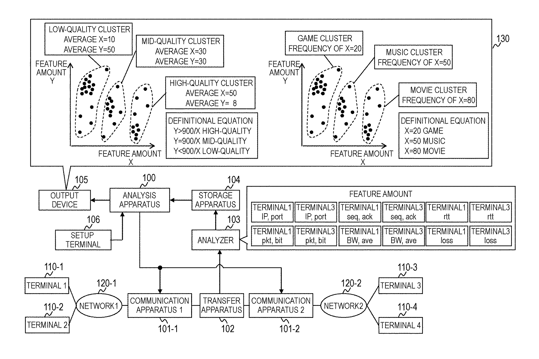
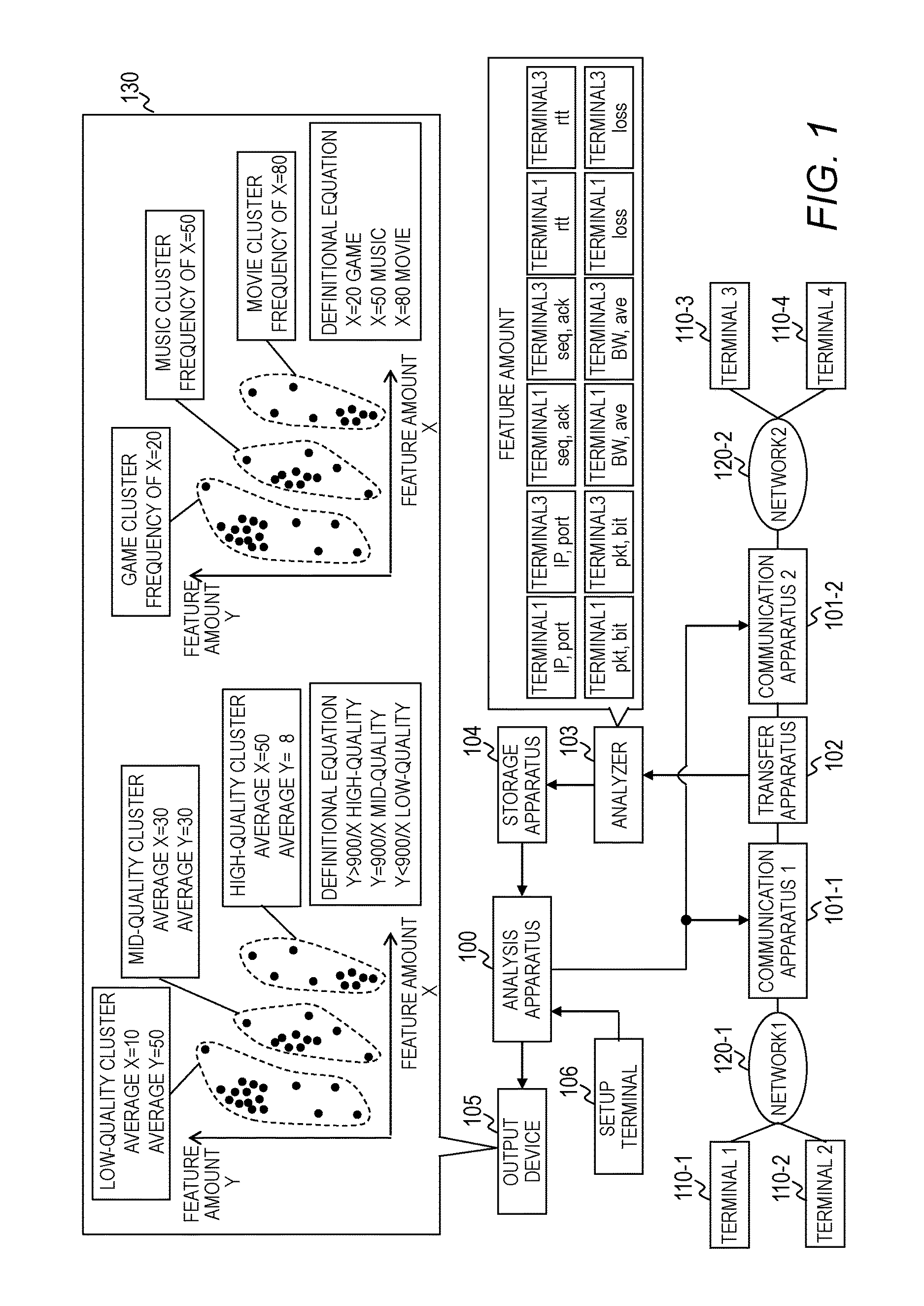
[0032]FIG. 1 is a diagram for explaining a configuration example of a network system of the first embodiment.

[0033]The network system of the first embodiment includes an analysis apparatus 100, a plurality of communication apparatuses 101, a transfer apparatus 102, an analyzer 103, a storage apparatus 104, an output device 105, a setup terminal 106, and a plurality of terminals 110.

[0034]The network system shown in FIG. 1 includes two communication apparatuses 1 (101-1) and 2 (101-2), and four terminals 1 (110-1), 2 (110-2), 3 (110-3), and 4 (110-4). Hereinafter, when it is not necessary to differentiate the communication apparatus 1 (101-1) from the communication apparatus 2 (101-2), the two are collectively referred to as communication apparatus 101, and when it is not necessary to differentiate the ...

second embodiment

[0133]The second embodiment differs from the first embodiment in that the cluster classification definition information 320 and the cluster history information 321 include clusters that have no action applied thereto. The second embodiment also differs from the first embodiment in that the analysis apparatus 100 executes an identified action. Below, the second embodiment will be explained, mainly focusing on the differences from the first embodiment.

[0134]The configuration of the network system and the analysis apparatus 100 of the second embodiment are the same as those of the first embodiment. The configurations of the packet, cluster classification definition information 320, and cluster history information 321 of the second embodiment are the same as those of the first embodiment. However, the action 405 and the action 414 differ from those of the first embodiment.

[0135]For example, in the action 405 of at least one entry of the cluster classification definition information 320 ...

third embodiment

[0150]In the third embodiment, the specific process of the analysis apparatus 100 will be explained using the detection of DDoS attack as an example. The configurations of the network system and analysis apparatus 100 of the third embodiment are the same as those of the first embodiment, and the information managed by the analysis apparatus 100, the analyzer 103, and the storage apparatus 104 of the third embodiment are the same as those of the first embodiment.

[0151]FIG. 10 is a flowchart for explaining an example of the process performed by the analysis apparatus 100 of the third embodiment in order to detect DDoS attack. FIG. 11 is a diagram for explaining one example of the feature amount history management information 600 of the third embodiment. For convenience, only a part of the columns of the feature amount history management information 600 is displayed in the third embodiment. FIG. 12 is a diagram showing an example of the process results of cluster analysis in the third ...


PUM


Abstract

A network system comprising a plurality of communication apparatuses, wherein the network system includes an analysis part for analyzing a communication flow to classify a plurality of communication flows by communication types. The analysis part includes: a feature amount obtaining part for obtaining, for each of the plurality of communication flows, management information on the communication flow including a plurality of feature amounts; a cluster analysis part for analyzing the management information on the communication flow to generate a plurality of clusters each made up of the plurality of communication flows; and a cluster classification part for classifying the plurality of clusters by communication types based on an analysis result obtained using at least one of the plurality of feature amounts of the plurality of communication flows included in each of the plurality of clusters.

Description

CLAIM OF PRIORITY[0001]The present application claims priority from Japanese patent application JP 2015-155363 filed on Aug. 5, 2015, the content of which is hereby incorporated by reference into this application.BACKGROUND OF THE INVENTION[0002]The present invention relates to a network system, classification method, and apparatus configured to classify a communication flow by the type of communication using feature amounts of each communication flow.[0003]A communication apparatus measures communication quality or communication speed of a communication flow by analyzing the packets of the communication flow, classifies the communication flow by the type of communication based on the measurement result, and actively applies various communication services based on the classification result. Examples of the technique to classify the communication flow include the technique disclosed in Japanese Patent Application Laid-open Publication No. 2014-154888 A is known.[0004]Japanese Patent ...

Claims


Application Information

Patent Timeline
Patent Type & Authority Applications(United States)
IPC IPC(8): H04L12/801H04L12/715H04L12/24
CPCH04L47/29H04L45/46H04L41/0893H04L43/08H04L41/06H04L41/142H04L43/04H04L47/2441
Inventor ISOBE, TAKASHI
Owner HITACHI LTD
Why Eureka
Try Eureka