
Tray

a technology for trays and trays, which is applied in the field of trays, can solve the problems of messy placing of items in your lap, inconvenient eating in the automobile, and inconvenient storage, and achieve the effect of improving storage possibilities

Inactive Publication Date: 2017-02-16
CM INVENTION
View PDF4 Cites 0 Cited by
  • Summary
  • Abstract
  • Description
  • Claims
  • Application Information

AI Technical Summary

Benefits of technology

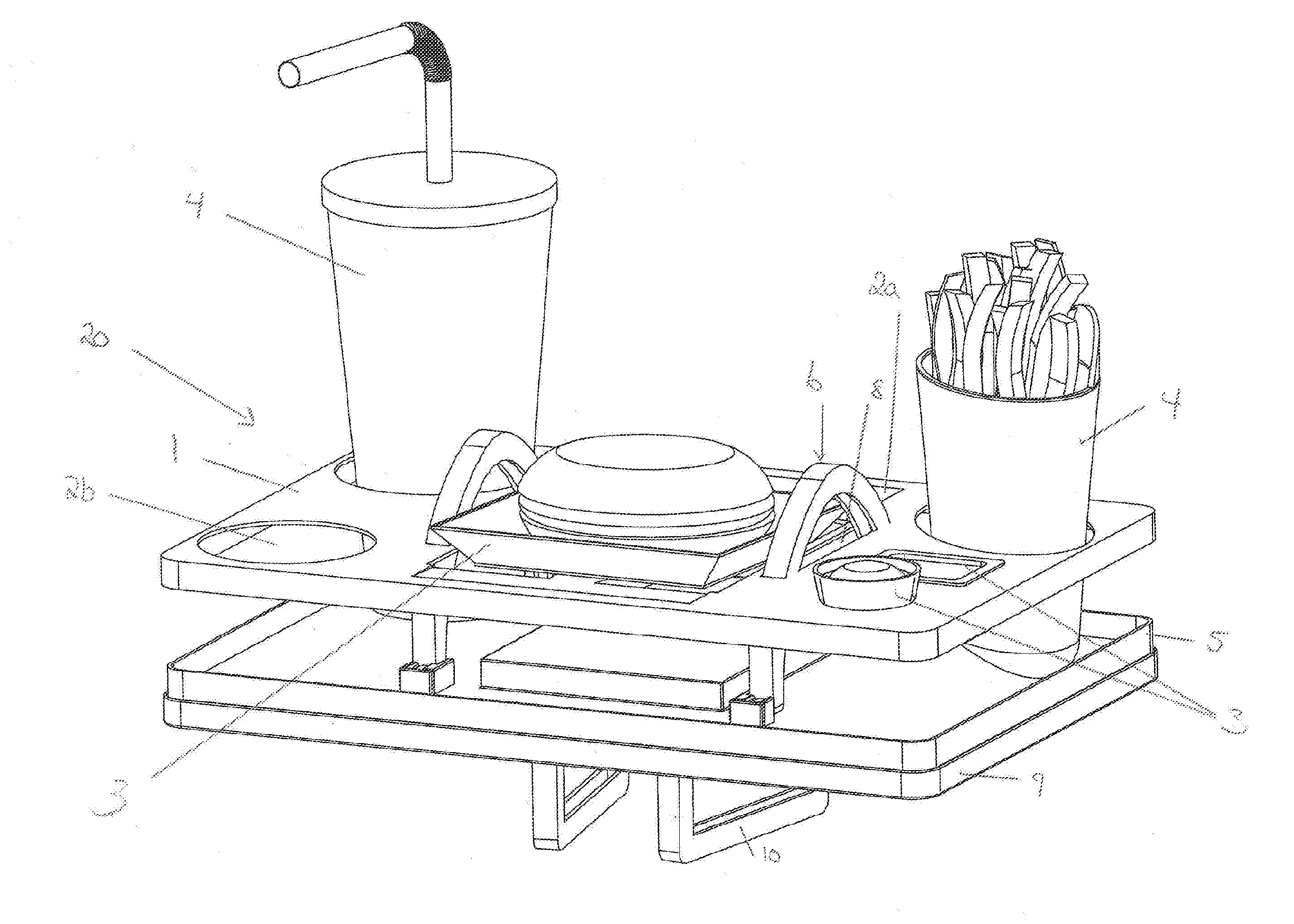
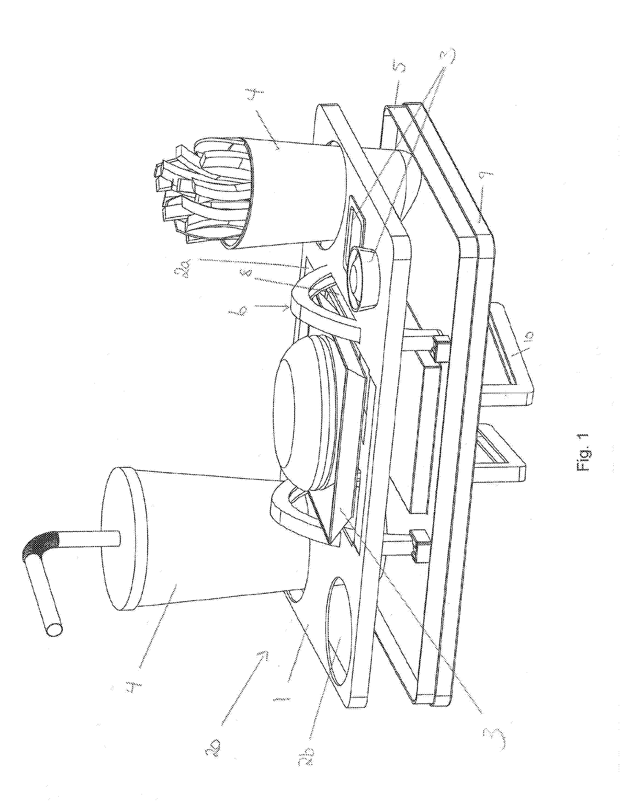
The invention is a tray that can be extended for good lateral support or retracted for easy storage or use as a tray for playing, drawing, homework, supporting tablets or books, etc. The tray has at least one antiskid element on the side facing away from the lateral support plate, which provides better support when the tray is placed in the lap.

Problems solved by technology

Unfortunately, many people find that eating in an automobile or, for instance, at the ball field, is not convenient and poses certain difficulties such as where to put the sandwich, where to put the French fries, where to put the ketchup and sauces.
Placing these items in your lap can be messy at any time and even hazardous while driving.
In conventional travel trays there are no support for the food or beverage containers and while carrying the tray, or balancing it on the lap, the open food containers can easily tilt and spill.
The base plate and the drinking bands do not form a flat surface when the tray is in collapsible position and are therefore not suitable for use as a playboard as a support for other item, like book for drawing, writing etc.

Method used


Image

  • Tray
  • Tray
  • Tray

Examples


second embodiment

[0103]FIG. 18-29 shows a tray according to the invention.

[0104]FIG. 18-19 are illustrating the tray with items, such as containers for food 3 or beverage 4, viewed from different angles. In this embodiment the tray 100 comprising a lateral support plate 101 with openings 103 (shown in FIG. 20). The openings 103 could have different configuration suitable for any shape of the containers of food or beverage 3, 4. For instance, there could be one opening suitable for a drinking cup, one opening suitable for a container with food, one opening suitable for sauce or other flavorings, etc. there could also be grooves or openings for pencils or support for tablet, books etc. The tray 100 is in this position in a first expanded spaced apart position.

[0105]The lateral support plate 101 is connected to a base plate 102 arranged beneath the lateral support plate 101. The lateral support plate 101 and the base plate 102 are connected together through at least one connection member 122. This conn...

first embodiment

[0145]FIG. 28 shows the support members arranged on the side of the base plate facing away from the lateral support plate 101. The Figures shows the support member 110 in a position where the support members 110 are arranged perpendicular to the base plate 102. The support members 110 could be attached to the base plate 102 through a snap coupling for instance clamps 120 arranged in pairs. The figure shows two pair of clamps connecting each support member to the base plate 101. Other fastening means are also possible for instance the fastening means as described in the invention.

[0146]FIG. 29 shows the support member 110 arranged in the grooves 114 (FIG. 28) in the base plate 102. The support member 110 could also be connected to the base plate 102 in an additional releasably connection 121 when the support member 110 is arranged in the grooves 114 to prevent the support members 110 to escape from the grooves 119 when the support members 110 are not in use. The arrangement of the su...


PUM


Abstract

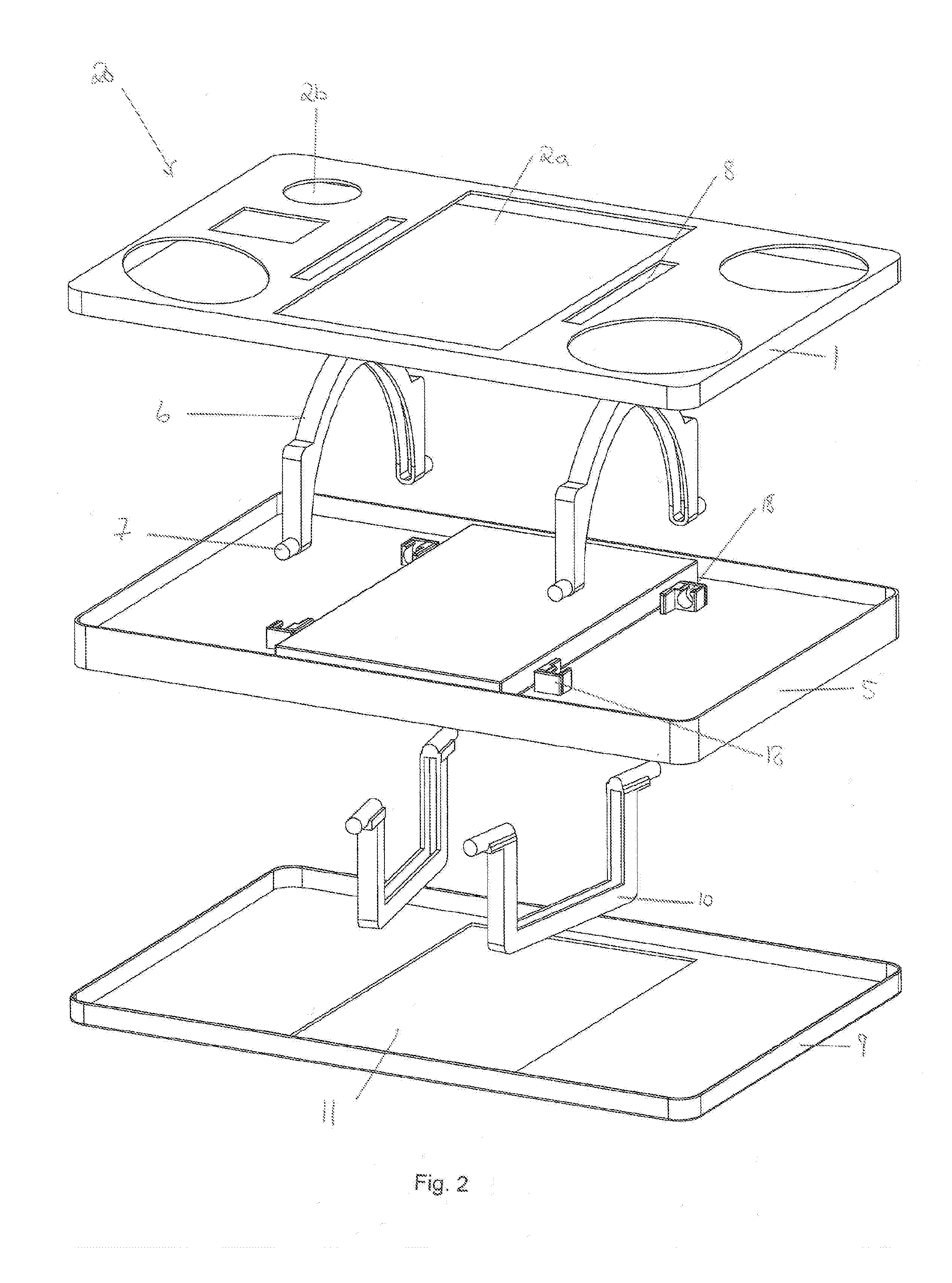
The invention relates to a tray for holding items, such as containers of food or beverage, said tray comprising a lateral support plate (1; 101) and a base plate (5; 102) arranged in a substantially parallel relationship, the tray further having spacing and locking means (6; 25, 122; 104, 105, 106, 107), said spacing and locking means (6; 25, 122, 104, 105, 106, 107) interconnecting the lateral support plate (1; 101) and the base plate (5; 102). The invention is distinctive in the lateral support plate (1; 101) having at least one opening (2a; 2b; 103) being defined through said lateral support plate (1, 101), forming lateral support for at least one item (3; 4). The base plate (5; 102) defining a supportive floor for the at least one item (3; 4), said spacing and locking means (6; 103) being configured to hold said lateral support plate (1; 101) and said base plate (5; 102) in a first extended spaced apart position and to hold said lateral support plate (1; 101) and said base plate (5; 102) in a second retracted position. The base plate (5; 102) having at least one elevated portion (17; 110) corresponding with the at least one opening (2a; 2b; 103) in the lateral support plate (1; 101), said elevated portion (17; 110) filling said opening in said second retracted position.

Description

FIELD OF THE INVENTION[0001]The invention herein pertains dining trays and particularly pertains to a dining tray that will provide support for various shaped containers for food or beverages stay positioned on the dining tray during use. The invention also pertains a tray that can be converted into having a flat surface and that is suitable for drawing, writing or similar activities.BACKGROUND OF THE INVENTION AND OBJECTIVES OF THE INVENTION[0002]Due to the fast-paced life style of the world we live in, it has become common practice for millions of people each day to grab a bite to eat on the go. Travelling to and from work, running errands, picking up the kids and shuffling them back and forth to school and extracurricular activities, taking long trips, are examples of times when a sit down meal at home may not be possible. We find ourselves instead eating in our automobiles or bringing our food along with us to eat while watching the kids play soccer or participate in some other ...

Claims


Application Information

Patent Timeline
Patent Type & Authority Applications(United States)
IPC IPC(8): A47G23/06A47B23/00
CPCA47G23/0641A47G23/0608A47B23/002A47B23/001A47G23/06
Inventor CHRISTOFFERSEN, KJETIL
Owner CM INVENTION
Learn More