Reflecting structure for lamp

Active Publication Date: 2017-02-16
TAIWAN NETWORK COMP & ELECTRONICS
View PDF3 Cites 0 Cited by
  • Summary
  • Abstract
  • Description
  • Claims
  • Application Information

AI Technical Summary

Benefits of technology

The invention provides a reflecting structure that improves the brightness of certain regions.

Problems solved by technology

Although the reflecting structures prevent light from dazzling eyes of a driver in a coming vehicle and control the illuminating range of a lamp so as to raise illuminating efficiency, the illuminating range is semi-circular which is a kind of and cannot satisfy illuminating ranges of various vehicles.

Method used


Image

  • Reflecting structure for lamp
  • Reflecting structure for lamp
  • Reflecting structure for lamp

Examples


Embodiment Construction

[0052]The following description is of the best-contemplated mode of carrying out the invention. This description is made for the purpose of illustrating the general principles of the invention and should not be taken in a limiting sense. The scope of the invention is best determined by reference to the appended claims.

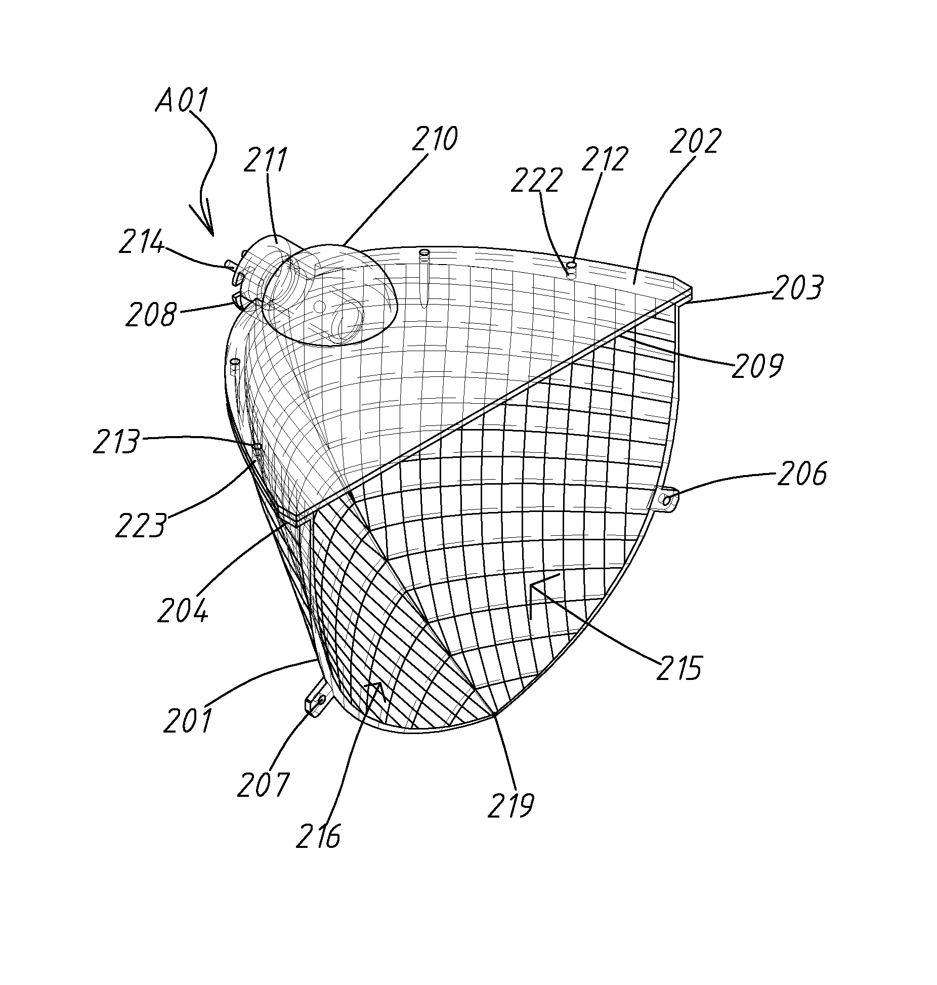
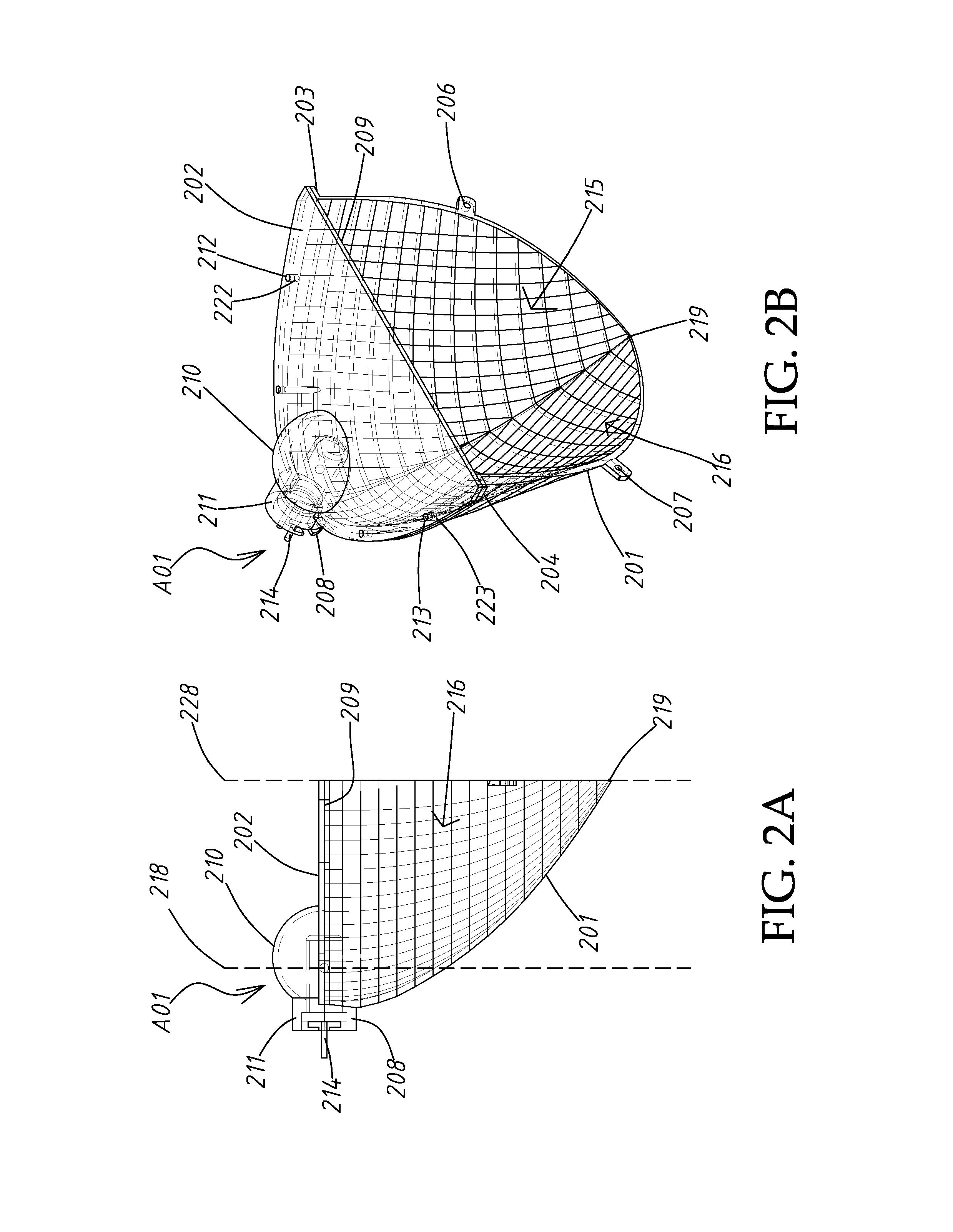
[0053]Referring to FIGS. 2A, 2B and 2C, a reflector A01 has an inner surface serving as a reflecting surface. The reflector A01 includes a main body 201 and a light intercepting plate 202. A light source 214 which can be a bulb, a light tube or LED is disposed in the reflector A01. The light intercepting plate 202 includes a light intercepting surface 209 intercepting light from the light source 214. In this embodiment, the light intercepting surface 209 is an inner surface of the light intercepting plate 202 and is a horizontal plane. The light intercepting plate 202 further includes an arced surface 210 extending from the light intercepting surface 209 and perpendicu...


PUM


Abstract

A reflecting structure includes at least one light source; and a reflector, in which the light source is disposed to emit light, including at least one light intercepting plate and a main body, wherein the light intercepting plate includes an inner surface which is a plane serving as a light intercepting surface intercepting the light from the light source, at least one reflecting surface extending from the light intercepting surface and perpendicularly toward an outer surface of the light intercepting plate and at least one positioning structure; the main body is joined to the light intercepting surface and includes at least two convex curved surfaces disposed on two opposite sides of a vertical line extending through the light source to reflect light from the light source directly and the light reflected by the light intercepting surface.

Description

BACKGROUND OF THE INVENTION[0001]Field of the Invention[0002]The invention relates to a reflecting structure for a lamp, and in particular to a lamp used in vehicles and streets and reflecting all light to a region to be illuminated, wherein an illuminating range is adjustable.[0003]Description of the Related Art[0004]Referring to FIGS. 1A and 1B, two conventional reflecting structures are depicted. A reflector B01 shown in FIG. 1A includes a light intercepting plate 101 which includes a light intercepting surface 102. At least one arced reflecting surface 103 is disposed on the light intercepting surface 102. A main body 104 is disposed under the light intercepting plate 102. The main body 104 includes a conical curved reflecting surface 112. A light source 105 is disposed at the top of the reflector B01 through a hole. The reflector B02 as shown in FIG. 1B includes a light intercepting plate 106. The light intercepting plate 106 includes a light intercepting surface 107. An arced ...

Claims


Application Information

Patent Timeline
IPC IPC(8): F21V13/04F21V15/01F21V7/04F21W107/00F21W107/10
CPCF21V13/04F21V15/01F21V7/04F21V7/048F21V7/09F21S41/336F21S41/337F21Y2115/10Y10S362/80
Inventor PENG, CHIA-MEICHUANG, HSIEH-CHENCHUANG, PING-HAN
Owner TAIWAN NETWORK COMP & ELECTRONICS
Why Eureka
Try Eureka