Surface light source element and image display apparatus including the same
Inactive Publication Date: 2012-04-17
KURARAY CO LTD
View PDF14 Cites 1 Cited by
Summary
Abstract
Description
Claims
Application Information
AI Technical Summary
This helps you quickly interpret patents by identifying the three key elements:
Problems solved by technology
Method used
Benefits of technology
Benefits of technology
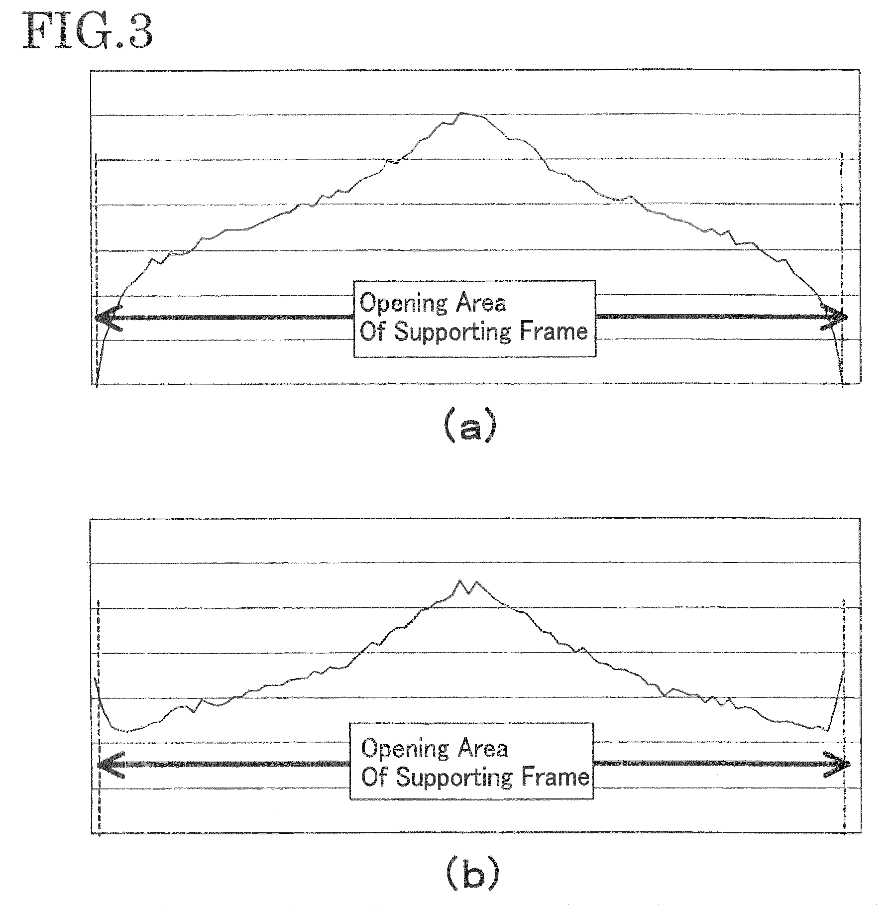
[0023]The surface light source element according to the first invention is an edge-light type surface light source element. The concave stripes provided in the bottom surface opposite to the exit surface of the light-guiding plate included in the surface light source element according to the present invention are arranged based on a position satisfying the following equation, if a distance which is from the opening boundary of the supporting frame of the liquid crystal panel into the back surface of the supporting frame is L. The surface light source element has a function, by adjusting an angle θ to be 20° to 60°, to enhance brightness at a central portion of the light-guiding plate and inhibit light leakage at a boundary of the supporting frame of the liquid crystal panel.
[0024]As the aforementioned second invention, if the primary light sources are disposed on the opposite two incident end surfaces of the light-guiding plate, respectively, it is possible to achieve high incident efficiency of light from the primary light sources into the incident end surfaces, and reduce a thickness of light-guiding plate when having the same brightness performance because lights are entered the two incident end surfaces, thus to be thin the surface light source element, compared with two primary light sources provided on one incident end surface. In addition, because incident end surfaces are provided on the both ends of the light-guiding plate, surface brightness distribution in a light-emitting area on a central line between one incident end surface and another incident end surface opposite to the one incident end surface may be adjusted. Thereby, it is possible to achieve easily equalization of surface brightness distribution, compared with a light-guiding plate having one incident end surface.
[0025]As the aforementioned third invention, if each of the concave stripes provided in the bottom surface of the light-guiding plate has a V-character shape in section, of lights guided in the light-guiding plate, it is possible to emit light directly entered inclined surfaces of each of t
Problems solved by technology
However, there is a problem that the number of light sources increases and with the increment, power consumption is increased.
In addition, because a thin diffusion plate is used for a light-emitting surface, if the diffusion plate and a primary light source located at a back surface of the diffusion plate are too close, there is a problem that variation in bright and dark of the light source is entered the light-emitting surface.
Consequently, there is a limitation to form a thinned light-guiding plate.
Therefore, although an edge-light ty
Method used
Image
Click on the blue label to locate the original text in one second.
Reading with bidirectional positioning of images and text.
Examples
Example
COMPARISON EXAMPLE 1
The comparison example is an example of a case where the angle θ in each of the V-character shaped concave stripes provided in the bottom surface of the light-guiding plate used in the embodiment 1 is 71°.
[0093]Similarly to the embodiment 1, a nickel electroformed layer was formed by making directly V-character shaped concave stripes each having 0.02 mm in height and 100° in top angle in a master mold by use of a diamond byte through a cutting process, and performing direct electroforming from the master mold. By removing a master, a stamper V of a bottom surface side and in which prism patterns each having 0.02 mm in height and 100° in top angle were arranged at predetermined intervals and finished was manufactured.
[0094]As molds, the stamper I used in the embodiment 1 and the stamper V were assembled in a mold stationary side cavity and a mold movable side cavity of an injection machine, and a light-guiding plate having a fine structure for a 32 inch-liquid cry...
Example
COMPARISON EXAMPLE 2
The comparison example is an example of a case where the angle θ in each of the V-character shaped concave stripes provided in the bottom surface of the light-guiding plate used in the embodiment 2 is 71°.
[0098]Similarly to the embodiment 2, a nickel electroformed layer was formed by making directly V-character shaped concave stripes each having 0.02 mm in height and 100° in top angle in a master mold by use of a diamond byte through a cutting process, and performing direct electroforming from the master mold. By removing a master, a stamper VI of a bottom surface side and in which prism patterns each having 0.02 mm in height and 100° in top angle were arranged at predetermined intervals and finished was manufactured.
[0099]As molds, the stamper III used in the embodiment 2 and forming the patterns of the V-character shaped convex stripes in section on the exit surface and the stamper VI were assembled in a mold stationary side cavity and a mold movable side cavit...
Example
COMPARISON EXAMPLE 3
[0103]The comparison example is an example of a case where the angle θ in each of the V-character shaped concave stripes provided in the bottom surface of the light-guiding plate used in the embodiment is 6°.
[0104]Similarly to the embodiment 1, a nickel electroformed layer was formed by making directly V-character shaped concave stripes each having 0.02 mm in height and 100° in top angle in a master mold obtained by use of a diamond byte through a lathe turning, and performing direct electroforming from the master mold. By removing a master, a stamper IX of a bottom surface side and in which prism patterns each having 0.02 mm in height and 100° in top angle were arranged at predetermined intervals and finished was manufactured.
[0105]As molds, the stamper III used in the embodiment 2 and forming trapezoidal convex patterns on the exit surface and the stamper IX were assembled in a mold stationary side cavity and a mold movable side cavity of an injection machine, ...
PUM
Abstract
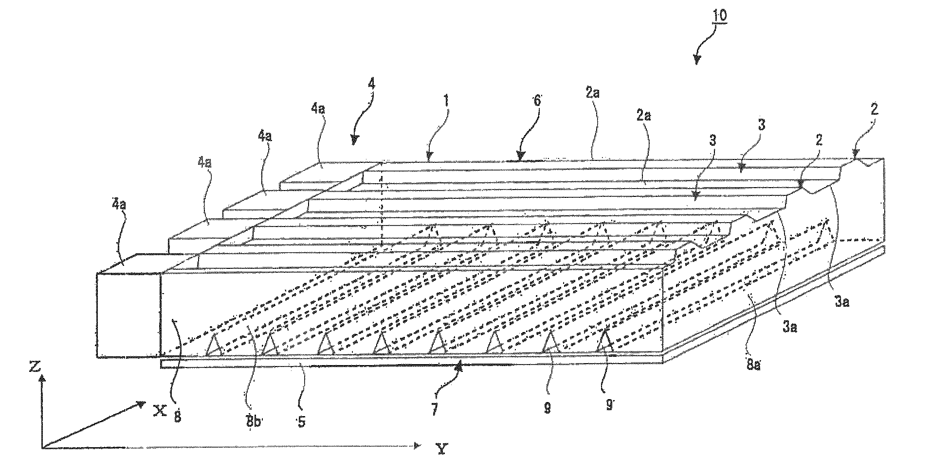
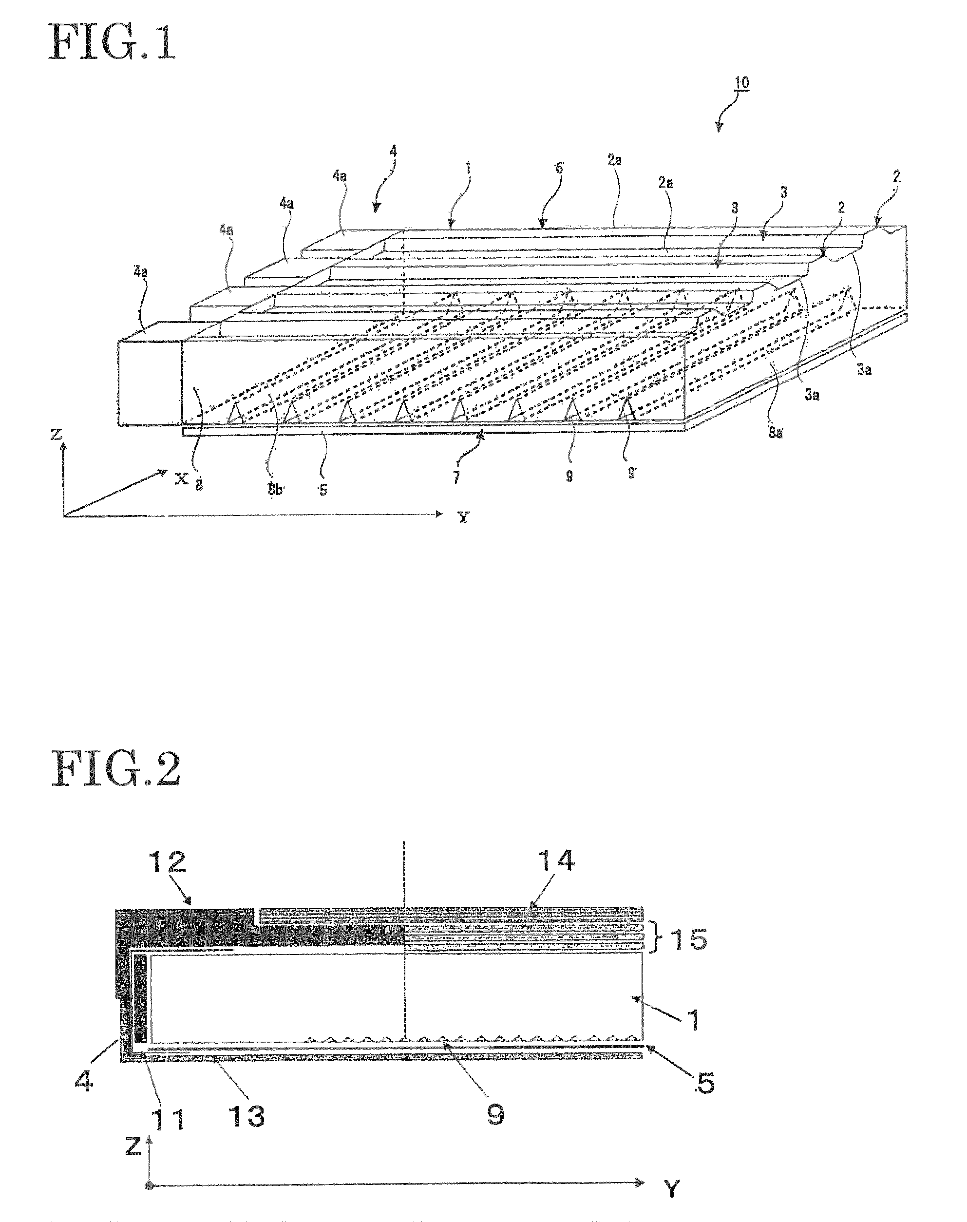
An object of the present invention is to provide a surface light source element configured to enhance projection light from an opening boundary of a supporting frame (12), wherein the projection light is required as a surface light source element, so that the surface light source element makes it possible to clearly illuminate an observation direction even in the case where the surface light source element is made large in size or thin in thickness. In the surface light source element using a light-guiding plate (1) provided with a prism pattern of a groove (9) that is V-character-like in section on a side of the bottom surface (7), the light-guiding plate (1) is characterized in comprising the prism pattern that enters from the edge of an opening of a supporting frame (12) to the incident edge surface side, wherein the prism pattern is arranged in a central direction of the light guide plate from a position of an angle θ ranging from 20° to 60° expressed by the following equation: L=T×tan θ where T: a thickness (mm) of the light guide plate (1), and L: a distance (mm) entering from the edge of the opening at the supporting frame (12) on an inner side of a liquid crystal panel to a back surface of the supporting frame (12).
Description
TECHNICAL FIELD[0001]The present invention relates to an edge-light type surface light source element having a plurality of primary light sources, and an image display apparatus using the same, more specifically to an edge-light type surface light source element used for liquid crystal display devices to which a high image quality is requested, illuminated sign devices or the like, and an image display apparatus using the edge-light type surface light source element.BACKGROUND ART[0002]There have been used two types, beneath-light type and edge-light type surface light source elements for an image display apparatus.[0003]The beneath-light type surface light source element includes a plate-like member provided with a light-emitting surface and a plurality of primary light sources disposed on a back surface of the plate-like member. This type has a characteristic that it is easy to be large in size because the light sources are disposed on the back surface opposite to the light-emitti...
Claims
Application Information
Patent Timeline
Application Date:The date an application was filed.
Publication Date:The date a patent or application was officially published.
First Publication Date:The earliest publication date of a patent with the same application number.
Issue Date:Publication date of the patent grant document.
PCT Entry Date:The Entry date of PCT National Phase.
Estimated Expiry Date:The statutory expiry date of a patent right according to the Patent Law, and it is the longest term of protection that the patent right can achieve without the termination of the patent right due to other reasons(Term extension factor has been taken into account ).
Invalid Date:Actual expiry date is based on effective date or publication date of legal transaction data of invalid patent.

