Apparatus of Detecting Transmittance of Trench on Infrared-Transmittable Material and Method Thereof

Active Publication Date: 2017-02-16
NAT APPLIED RES LAB
View PDF8 Cites 6 Cited by
  • Summary
  • Abstract
  • Description
  • Claims
  • Application Information

AI Technical Summary

Benefits of technology

[0007]The main purpose of the present invention is to detect transmittance of a trench on a wafer, where contrast of an image of the wafer is greatly enhanced for detection; a

Problems solved by technology

First, the ditching force may not be big enough. After ditching out a street on the wafer, defects of non-cut-through areas may appear. These defects would result in broken dies in the following process of die bonding.
Second, the ditching force may be excessive. After ditching out the street, areas near the street on the back of the die may be cracked.
Although these two types of defects formed after ditching the wafer can be effectively detected through scanning electron microscopy (SEM) before dicing the wafer, this kind of traditional detection is expensive and takes time.
Hence, it is not suitable for on-line detection and is hard to be automated.
However, the color of the wafer ditching tape and the capability of light transmission would have serious i

Method used


Image

  • Apparatus of Detecting Transmittance of Trench on Infrared-Transmittable Material and Method Thereof
  • Apparatus of Detecting Transmittance of Trench on Infrared-Transmittable Material and Method Thereof
  • Apparatus of Detecting Transmittance of Trench on Infrared-Transmittable Material and Method Thereof

Examples


Example

[0013]The following description of the preferred embodiment is provided to understand the features and the structures of the present invention.

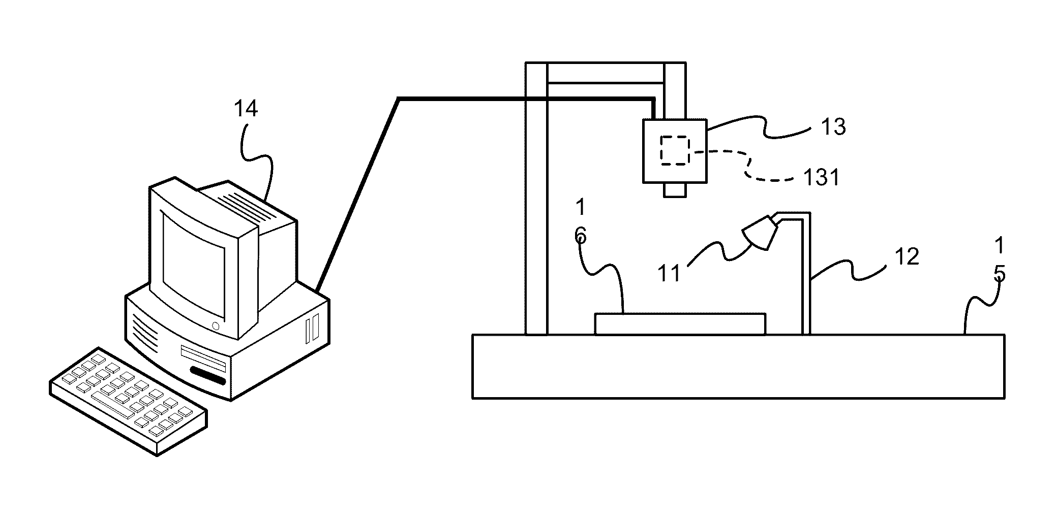
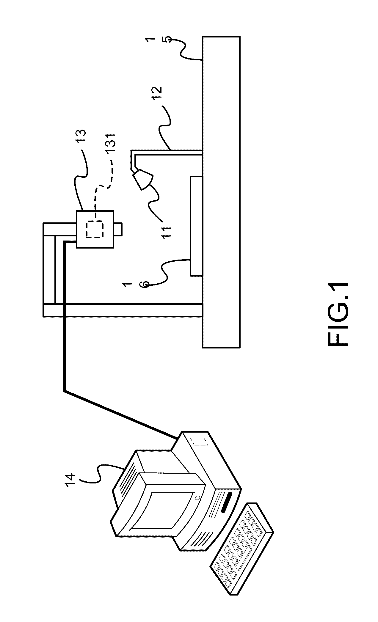
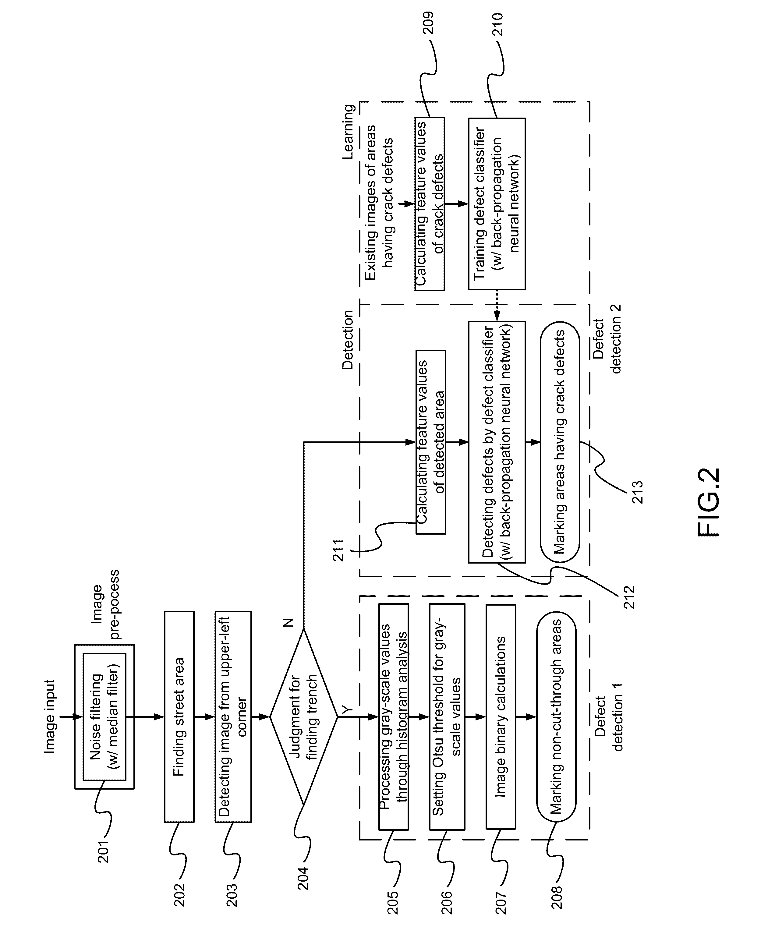
[0014]Please refer to FIG. 1 and FIG. 2, which are a view showing a preferred embodiment according to the present invention; and a view showing a method using the preferred embodiment. As shown in the figures, the present invention is an apparatus of detecting transmittance of a trench on an infrared-transmittable material and a method thereof. As shown in FIG. 1, the apparatus comprises a light source 11, an adjustable fixing support 12, a light intensity sensor 13, and a trench-transmittance analysis unit 14.

[0015]The light source 11 emits a visible light and an infrared light to be projected onto a wafer 16 having a trench obtained after ditching.

[0016]The adjustable fixing support 12 has an end set on a base and another end connected to the light source 11 to control the light source 11 shining on the wafer 16 at an angle.

[0017]The light ...


PUM


Abstract

An apparatus is provided for detecting transmittance of a trench. The trench is located on an infrared-transmittable material, which can be a wafer. The wafer is obtained after a ditching process. An image of the wafer is fetched. The contrast of the image is greatly enhanced. The contrast-enhanced image is used for automated analysis of the transmittance of the trench. Accuracy of detecting the transmittance is improved. Hence, the present invention uses a simple structure to detect transmittance defects of the trench for ensuring goodness of the wafer.

Description

TECHNICAL FIELD OF THE INVENTION[0001]The present invention relates to detecting transmittance of trench; more particularly, relates to detecting transmittance of a trench on a wafer obtained after a ditching process, where contrast of an image of the wafer is greatly enhanced for detection; automatic infrared analysis of transmittance of the trench is processed with the contrast-enhanced image; accuracy of detecting the transmittance of the trench is improved; and transmittance defects of the trench are detected for ensuring goodness of the wafer.DESCRIPTION OF THE RELATED ARTS[0002]During packaging an integrated circuit (IC) wafer and testing its function, defect detection devices are provided for the wafer before being diced, while few devices are provided for the wafer obtained after being diced. In fact, because the blade speed and ditching depth are hard to control, the following two situations may happen after the wafer is ditched:[0003]First, the ditching force may not be bi...

Claims


Application Information

Patent Timeline
IPC IPC(8): G01N21/59
CPCG01N2201/12G01N21/59G01N21/9501G01N21/9505G01N21/95692G01N2021/3155
Inventor LIN, CHUN-FUCHANG, CHUN-LILIAO, TAI-SHANHUANG, HUNG-JIHUANG, CHI-HUNG
Owner NAT APPLIED RES LAB
Why Eureka
Try Eureka