System and a method of adaptively controlling an LED backlight

Inactive Publication Date: 2013-06-27
HIMAX MEDIA SOLUTIONS
4 Cites 8 Cited by

AI-Extracted Technical Summary

Problems solved by technology

As the content of image data usually does not occupy its fully dynamic range, i.e., from the darkest to the brightest, a dynamic range of the displ...

Method used

[0023]In the embodiment, a content analyzer 12 is configured to analyze characteristics (e.g., luminance) of image data to be displayed on the display panel 11. Based on an analysis result of the content analyzer 12, an LED current controller 13 accordingly controls illumination of the LED backlight 10 via an LED driver (board) 14 that is used to drive the LED backlight 10. Specifically, the LED driver 14 includes a pulse-width-modulation (PWM) controller 141, which determines a duty cycle (of a PWM signal) during which the LEDs of the LED backlight 10 are turned on and thus illuminate the display panel 11. Accordingly, a PWM signal with a larger duty cycle allows more current flowing in the LEDs of the LED backlight 10 and the LED backlight 10 thus generates higher luminous intensity (i.e., brighter). On the other hand, a PWM signal with a smaller duty cycle allows less current flowing in the LEDs of the LED backlight 10 and the LED backlight 10 thus generates lower luminous intensity (i.e., dimmer). The LED driver 14 may further include a current limiter 142 that imposes an upper limit (e.g., via a register) on the current that may be delivered to the LED backlight 10 with the purpose of protecting the LEDS of the LED backlight 10 from overheating.
[0026]Alternately, as exemplified in FIG. 3C, the over-driving may be achieved by over-driving less amount of LEDs than the example in FIG. 3B. As a result, the dynamic range 25 of the over-driven display panel 11 is approximately the same as the normal dynamic range 24 of the display panel 11. Therefore, cost associated with cutting down the amount of LEDs can thus be reduced.
[0030]FIG. 6A shows a flow diagram illustrating a method of adaptively controlling an LED backlight 10 according to a fourth embodiment of the present invention, and FIG. 6B shows exemplary drive current variation with respect to time. Specifically, in step 61, drive current values are accumulated over a period Δ t, and then an average current value Iavg ...

Benefits of technology

[0009]In view of the foregoing, it is an object of the embodiment of the present invention to provide a system and method of adaptively controlling a l...

Abstract

The present invention is directed to a system and method of adaptively controlling a light-emitting diode (LED) backlight. A content analyzer analyzes luminance of image data to be displayed on a display panel. An LED current controller controls illumination of the LED backlight via an LED driver according to an analysis result of the content analyzer. The LED current controller over-drives the LED backlight such that a drive current flowing in the LED backlight is above a normal current, when the analysis result of the content analyzer indicates that the luminance of image data is above a predetermined value.

Application Domain

Technology Topic

Image

  • System and a method of adaptively controlling an LED backlight
  • System and a method of adaptively controlling an LED backlight
  • System and a method of adaptively controlling an LED backlight

Examples

  • Experimental program(1)

Example

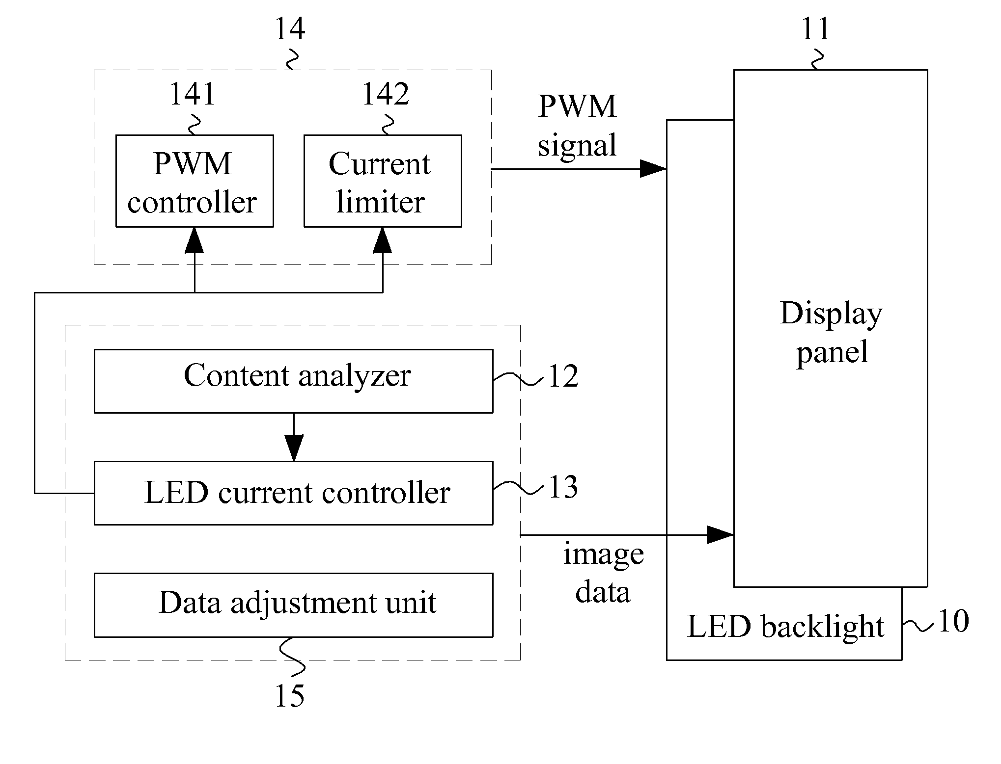
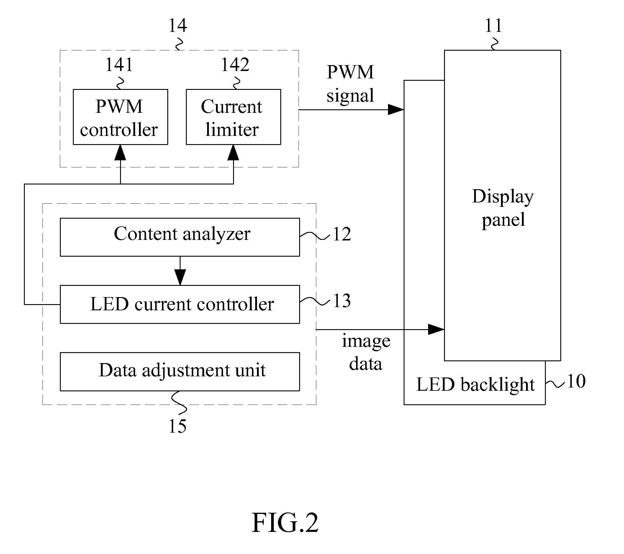
[0022]FIG. 2 shows a block diagram illustrating a system of adaptively controlling a light-emitting diode (LED) backlight 10 according to a first embodiment of the present invention. The system of the embodiment may be adapted to a display panel 11, such as a liquid crystal display (LCD) panel, which is illuminated by the LED backlight 10.
[0023]In the embodiment, a content analyzer 12 is configured to analyze characteristics (e.g., luminance) of image data to be displayed on the display panel 11. Based on an analysis result of the content analyzer 12, an LED current controller 13 accordingly controls illumination of the LED backlight 10 via an LED driver (board) 14 that is used to drive the LED backlight 10. Specifically, the LED driver 14 includes a pulse-width-modulation (PWM) controller 141, which determines a duty cycle (of a PWM signal) during which the LEDs of the LED backlight 10 are turned on and thus illuminate the display panel 11. Accordingly, a PWM signal with a larger duty cycle allows more current flowing in the LEDs of the LED backlight 10 and the LED backlight 10 thus generates higher luminous intensity (i.e., brighter). On the other hand, a PWM signal with a smaller duty cycle allows less current flowing in the LEDs of the LED backlight 10 and the LED backlight 10 thus generates lower luminous intensity (i.e., dimmer). The LED driver 14 may further include a current limiter 142 that imposes an upper limit (e.g., via a register) on the current that may be delivered to the LED backlight 10 with the purpose of protecting the LEDS of the LED backlight 10 from overheating.
[0024]In operation, when the analysis result of the content analyzer 12 indicates that the luminance of the image data is low (i.e., a dim image), the LED current controller 13 controls the PWM controller 141 in a manner such that the current flowing in the LEDs of the LED backlight 10 is below a normal current (e.g., a current recommended by an LED manufacturer). In other words, the LED backlight 10 is under-driven or operates at an under-drive mode. FIG. 3A shows relationship among a normal dynamic range of the display panel 11, a dynamic range of image content and a dynamic range of an under-driven display panel 11. As exemplified in FIG. 3A, the dynamic range 21 of a dim image constitutes only a small portion of a full dynamic range 22. After under-driving the LED backlight 10, the dynamic range 23 of the under-driven display panel 11 is thus substantially lower than the normal dynamic range 24 of the display. Therefore, considerable energy can be saved.
[0025]With respect to one aspect of the embodiment, when the analysis result of the content analyzer 12 indicates that the luminance of the image data is high (i.e., a bright image), the LED current controller 13 controls the PWM controller 141 in a manner such that the current flowing in the LEDs of the LED backlight 10 is above a normal current (e.g., the current recommended by an LED manufacturer). In other words, the LED backlight 10 is over-driven or operates at an over-drive mode. FIG. 3B shows relationship among a normal dynamic range of the display panel 11, a dynamic range of image content and a dynamic range of an over-driven display panel 11. As exemplified in FIG. 3B, the dynamic range 21 of a bright image constitutes a substantially large portion of a full dynamic range 22. After over-driving the LED backlight 10, the dynamic range 25 of the over-driven display panel 11 is thus higher than the normal dynamic range 24 of the display. Therefore, a dynamic contrast of the bright image can be increased.
[0026]Alternately, as exemplified in FIG. 3C, the over-driving may be achieved by over-driving less amount of LEDs than the example in FIG. 3B. As a result, the dynamic range 25 of the over-driven display panel 11 is approximately the same as the normal dynamic range 24 of the display panel 11. Therefore, cost associated with cutting down the amount of LEDs can thus be reduced.
[0027]It is noted that the content analyzer 12 and the LED current controller 13 as discussed above may be implemented in a timing-controller (T-CON) of a video system in hardware, software or their combination. The content analyzer 12 and the LED current controller 13 may, alternately, be implemented in a silicon-on-chip (SOC) processor that typically precedes the timing controller (T-CON) in the video system. The system of the embodiment may further include a data adjustment unit 15 that is utilized to adjust or re-map the dynamic range 21 (FIG. 3A/B/C) of an image to its full dynamic range 22, before the image data are fed to the display panel 11.
[0028]With another aspect of the embodiment, some schemes of protecting LEDs of an over-driven LED backlight 10 from overheating are proposed. FIG. 4 shows a block diagram illustrating a partial system of adaptively controlling an LED backlight 10 according to a second embodiment of the present invention. In the embodiment, a temperature estimate unit 16 is configured to estimate a temperature of an over-driven LED backlight 10, for example, according to the duty cycle of the PWM signal and time lapsed during over-driving as recorded by an over-drive timer 17. When the estimated temperature reaches a high temperature limit, indicating that excessively heat has been generated, the over-drive mode may be temporarily turned off (that is, a normal current is resumed instead), or the over-drive current is temporarily reduced.
[0029]FIG. 5 shows a block diagram illustrating a system of adaptively controlling an LED backlight 10 according to a third embodiment of the present invention. In the embodiment, a temperature sensor 18 is used to detect a temperature of an over-driven LED backlight 10. In case that the detected temperature is higher than a predetermined temperature threshold value, the over-drive current is temporarily reduced, for example, by reducing the duty cycle of the PWM signal.
[0030]FIG. 6A shows a flow diagram illustrating a method of adaptively controlling an LED backlight 10 according to a fourth embodiment of the present invention, and FIG. 6B shows exemplary drive current variation with respect to time. Specifically, in step 61, drive current values are accumulated over a period Δ t, and then an average current value Iavg is obtained, for example, dividing the accumulated current value by Δ t. In practice, the duty cycle of the PWM signal may be processed instead of the drive current for the reason that the drive current is typically in proportion to the duty cycle of the PWM signal. In step 62, the average current value Iavg is then compared with an upper limit Imax. If the average current value Iavg is not greater than the upper limit Imax, indicating that the LED backlight 10 is safe from overheating, the flow goes back to step 61 to accumulate drive current values and obtain another average current value Iavg over a succeeding period Δ t that is shifted slightly, in time, from the preceding period Δ t. If the average current value Iavg is determined, in step 62, to be greater than the upper limit Imax, the flow goes to step 63, in which the drive current is reduced to prevent the LED backlight 10 from overheating. Especially, step 63 proceeds gradually or step by step such that a viewer will not perceive an abrupt change in a displayed image. Subsequently, step 64 is performed, similar to step 61, to accumulate drive current values and obtain an average current value Iavg over a succeeding period Δ t. In step 65, the average current value Iavg is then compared with an upper limit Imax minus a hysteretic value Ih. If the average current value Iavg is not less than the upper limit minus the hysteretic value (i.e., Imax-Ih), indicating that the drive current has not been reduced enough, the flow goes back to perform steps 63 and 64 repeatedly until the average current value Iavg is less than the upper limit minus the hysteretic value (i.e., Iavg max-Ih), at that time, the flow proceeds to step 66, in which the drive current is increased to enhance the dynamic contrast of a bright image. Especially, step 66 proceeds gradually or step by step such that a viewer will not perceive an abrupt change in a displayed image. After completing step 66, the flow goes back to the beginning, i.e., step 61.
[0031]As the accumulation of the drive current values requires a buffer or memory to store the drive current values over a period Δ t, and the acquisition and comparison of the average drive current need computation capability, the fourth embodiment (FIG. 6A/B) as discussed above may preferably be implemented in the timing-controller (T-CON) or the silicon-on-chip (SOC) processor because of their available computation and memory sources. FIG. 7A shows a flow diagram illustrating a method of adaptively controlling an LED backlight 10 according to a fifth embodiment (that does not need a buffer for storing the drive current values) of the present invention, which may be adequately implemented in the LED driver (board) 14, which is typically lacking of sufficient computation and memory sources. FIG. 7B shows exemplary drive current variation with respect to time.
[0032]Specifically, in step 71, a first counter (or variable) CNT1 is used to enumerate or count a first accumulated drive current over a (small) unit period Δ t, and, in step 72, a second counter (or variable) CNT2 is used to enumerate or count a second accumulated drive current over a twofold period 2Δ t. The first half of the twofold period 2Δ t coincides with the unit period Δ t. In step 73, an average drive current is obtained according to the second accumulated drive current CNT2, for example, dividing CNT2 by the twofold period 2Δ t. Subsequently, in step 74, the difference between CNT2 and CNT1 is obtained and used as a new (or updated) CNT1. The flow goes back to step 72, in which a new (or updated) second accumulated drive current CNT2 is obtained over a new twofold period 2Δ t. The first half of the new twofold period coincides with the second half of the old (or original) twofold period. In the embodiment, the duty cycle of the PWM signal may be processed instead of the drive current. As shown in FIG. 7C, the duty cycle of the PWM signal may be derived, for example, by sampling the PWM signal by a sampling clock with a frequency higher than that of the PWM signal.
[0033]Although specific embodiments have been illustrated and described, it will be appreciated by those skilled in the art that various modifications may be made without departing from the scope of the present invention, which is intended to be limited solely by the appended claims.

PUM

no PUM

Description & Claims & Application Information

We can also present the details of the Description, Claims and Application information to help users get a comprehensive understanding of the technical details of the patent, such as background art, summary of invention, brief description of drawings, description of embodiments, and other original content. On the other hand, users can also determine the specific scope of protection of the technology through the list of claims; as well as understand the changes in the life cycle of the technology with the presentation of the patent timeline. Login to view more.

Similar technology patents

Imaging system

ActiveUS20140185752A1Enhance image contrastMaterial discrimination be also facilitateMaterial analysis by transmitting radiationRadiation diagnosticsPhysicsImage system
Owner:IND TECH RES INST

System and method for rapid focusing and analysis using a micro-camera array microscope

PendingUS20220179187A1Enhance image contrastMaximize performanceTelevision system detailsSolid-state devicesPhysicsCamera array
Owner:RAMONA OPTICS INC

System and method for the classification of healthiness index from chest radiographs of a healthy person

InactiveUS20170337681A1Enhance image contrastImage enhancementImage analysisComputer-aidedLung segmentation
Owner:SHENZHEN SMART IMAGING HEALTHCARE

Classification and recommendation of technical efficacy words

  • Enhance image contrast
  • Energy save

Dry etch stop process for eliminating electrical shorting in MRAM device structures

ActiveUS20070155027A1Enhance image contrastReduce reflectionSemiconductor/solid-state device manufacturingGalvano-magnetic device manufacture/treatmentElectrical ShortingEngineering
Owner:OEM GRP LLC

Imaging system

ActiveUS20140185752A1Enhance image contrastMaterial discrimination be also facilitateMaterial analysis by transmitting radiationRadiation diagnosticsPhysicsImage system
Owner:IND TECH RES INST

Programmable energy saving register vent

InactiveUS20070298706A1Energy saveReduce amount of energyDucting arrangementsMechanical apparatusLouverEngineering
Owner:SPRINGFIELD ACQUISITION CO LLC
Why Eureka
Try Eureka