Radiation image processing apparatus, image processing method, x-ray radioscopy apparatus and control method thereof

Inactive Publication Date: 2010-04-29
CANON KK
View PDF7 Cites 10 Cited by
  • Summary
  • Abstract
  • Description
  • Claims
  • Application Information

AI Technical Summary

Benefits of technology

[0009]The present invention provides a radiation image processing apparatus which is capable of determining whether there is a large amount of scattered radiation without being affected by a subject being imaged. Also, the present invention locally determines at each of the positions whether there is

Problems solved by technology

However, even when this anti-scattering grid is utilized, a large amount of scattered radiation which is scattered from the subject reaches the image sensor, and causes deterioration of image contrast.
S62-092662, it is not possible to accurately retrieve an amount corresponding to the scattered radiation merely by subtraction between pixels above which the grid exis

Method used


Image

  • Radiation image processing apparatus, image processing method, x-ray radioscopy apparatus and control method thereof
  • Radiation image processing apparatus, image processing method, x-ray radioscopy apparatus and control method thereof
  • Radiation image processing apparatus, image processing method, x-ray radioscopy apparatus and control method thereof

Examples


Example

Embodiment 1

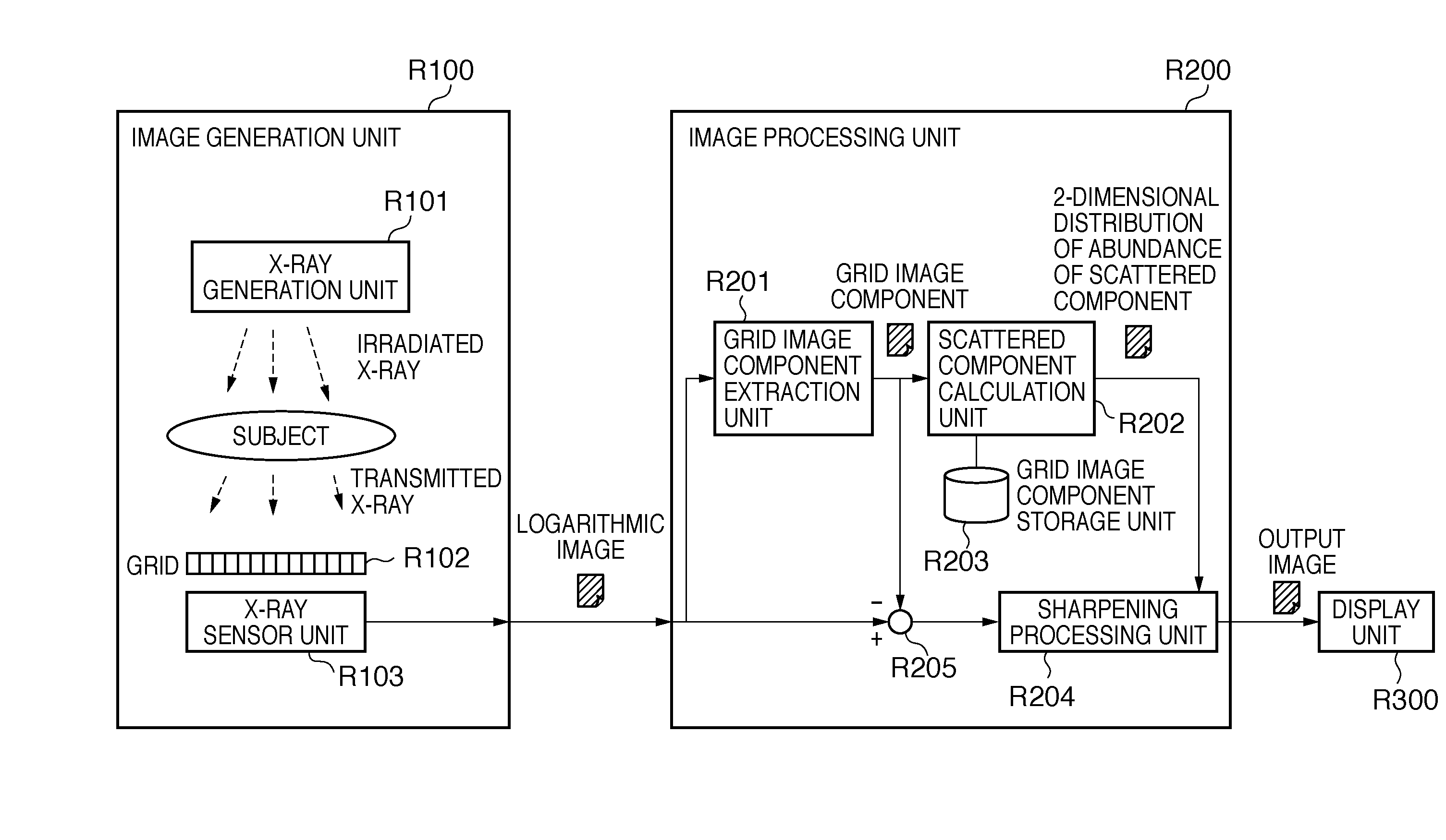
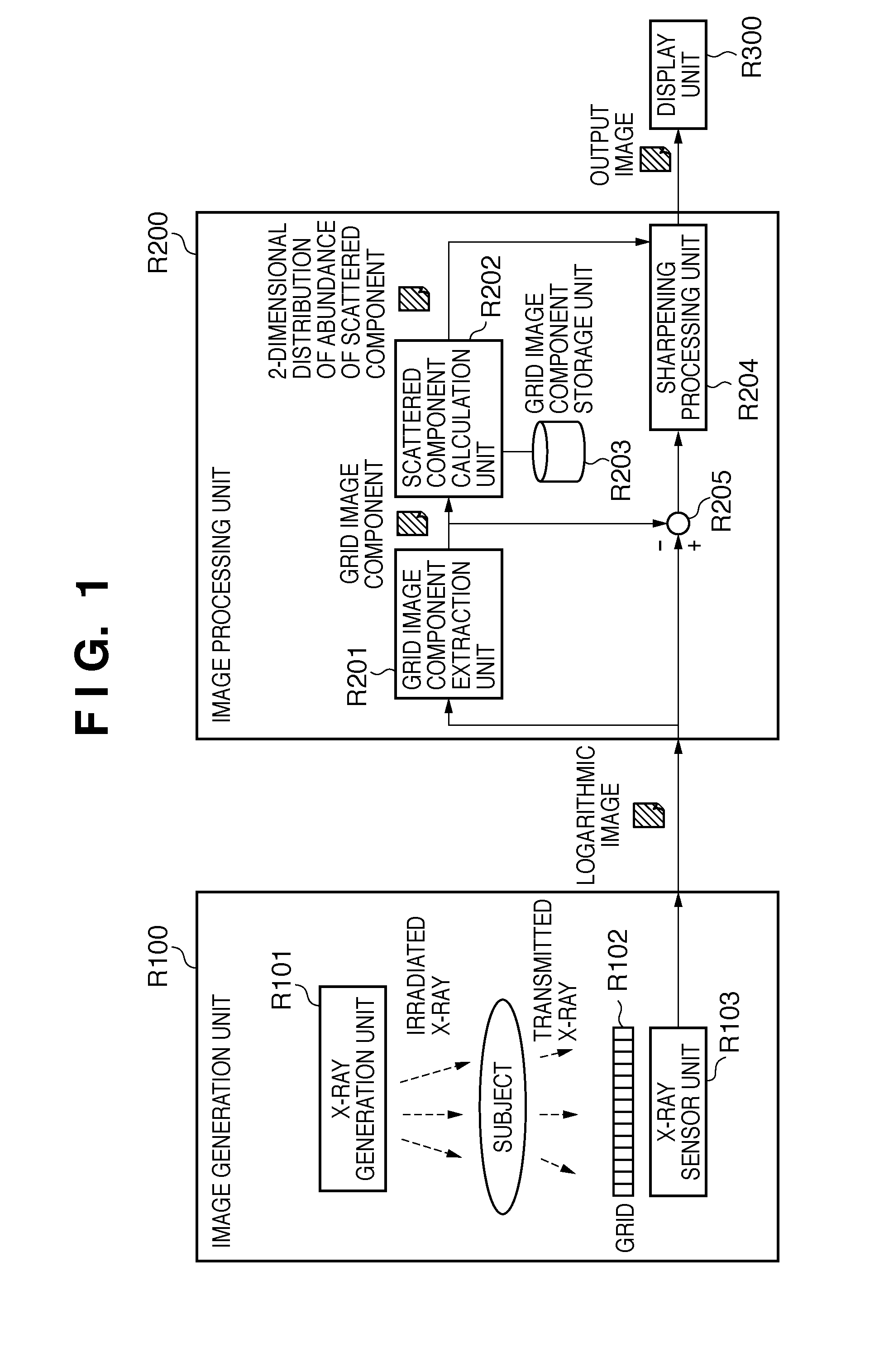
[0037]FIG. 1 is a block diagram showing functional configuration of a radiation image processing apparatus according to embodiment 1. FIGS. 10A and 10B are flow charts showing operation of the radiation image processing apparatus according to the present embodiment. FIG. 6 is a block diagram showing the hardware configuration of the radiation image processing apparatus according to the present embodiment. In the following, the function of each of the blocks in FIG. 1 will be explained in accordance with the order of the flowcharts shown in FIGS. 10A and 10B.

[0038]The program corresponding to each of the steps shown in FIGS. 10A and 10B is stored in a storage device such as a hard disc HD, a magneto-optical disc MO, a RAM or a ROM of a computer PC shown in FIG. 6. Actions described below are executed by the CPU reading out the program from the storage device, and executing the program in the order shown in the flow charts.

[0039]As an order of execution, the flow shown in ...

Example

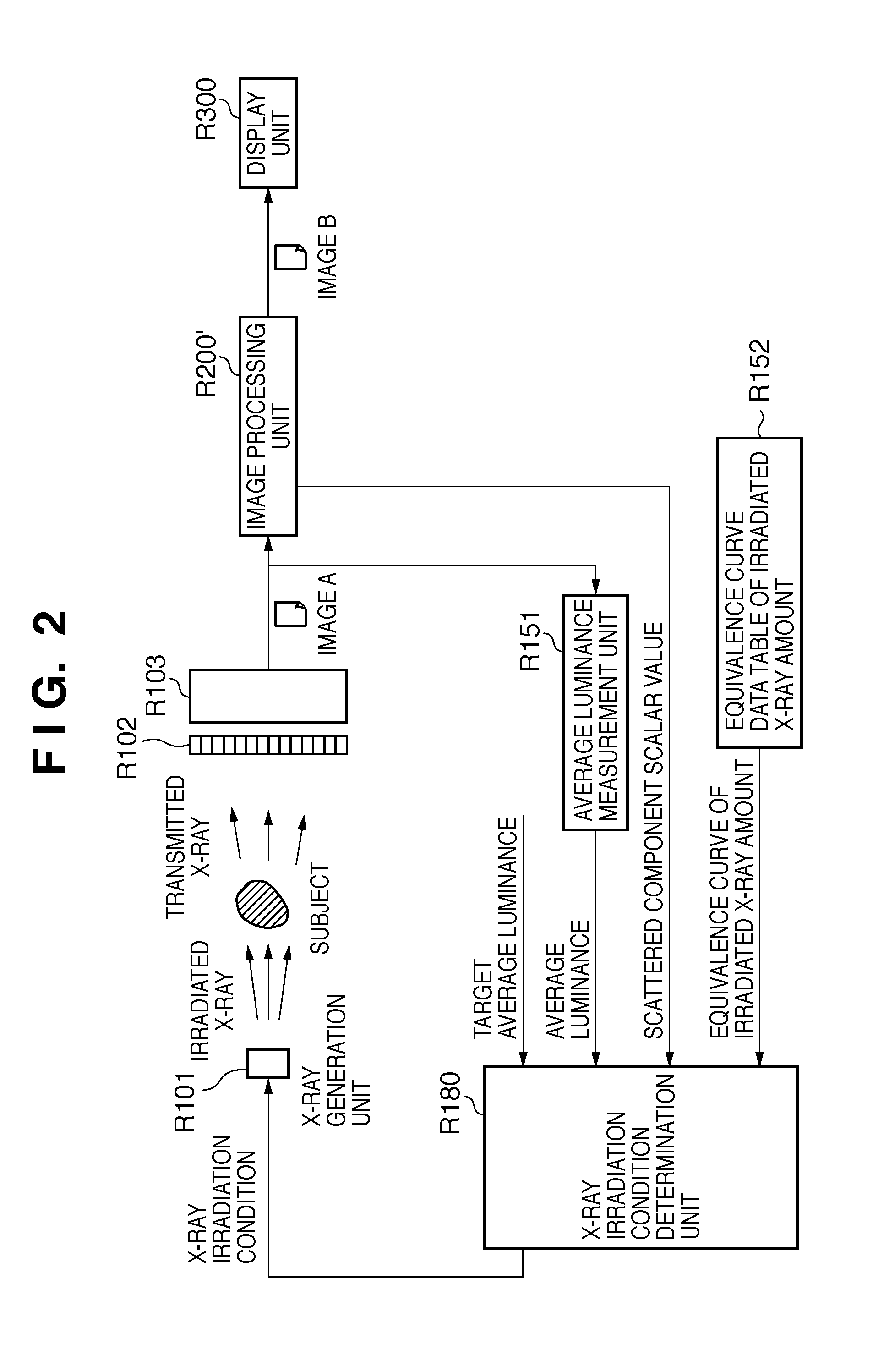
[0081]The configuration of the first embodiment discussed above is mainly for the purpose of improving contrast of radiation images. On the other hand, the configuration of a second embodiment to be explained below not only focuses on improvement in contrast of radiation images, but also aims to reduce operator's exposure to radiation.

[0082]An operator who is performing a surgery is exposed to radiation due to generation of scattered radiation from the subject, even if the operator is not directly irradiated. Since radiation exposure to scattered radiation is not direct, the amount of radiation the operator receives is smaller than the amount that the subject receives. However, even if the amount of radiation per operation may be small, daily exposure to radiation from the total operation time could add up to a very large.

[0083]The foremost priority during an operation is clarity with which the subject is seen, and image quality is dependent on tube voltage and tube current which to...


PUM


Abstract

A radiation image processing apparatus which improves contrast and sharpness of radiation images is provided. According to this radiation image processing apparatus, comparison is made between a first image data obtained by radiation imaging without going through the subject but through a grid for removing scattered radiation from a subject, and a second image data which is obtained by radiation imaging through the subject and the grid, and a two-dimensional distribution of abundance of scattered component is calculated. Using this two-dimensional distribution of scattered component, abundance of scattered radiation is locally determined at each position, and a sharpening process is performed with sharpening intensities that are increased in response to abundance of scattered radiation.

Description

BACKGROUND OF THE INVENTION[0001]1. Field of the Invention[0002]The present invention relates to a radiation image processing technique.[0003]2. Description of the Related Art[0004]When making observations of a subject (human body in particular) by detecting distribution of transmitted radiation such as X-rays that are transmitted through the subject, radiation imaging systems utilizing X-ray TV systems and accumulative fluorescent body (photostimulable phosphor) are used. In recent years, capturing of radiation images of a subject by directly receiving radiation that has been transmitted through a subject with a flat panel X-ray sensor, a large-scale image sensor (solid-state image sensor) that utilizes semiconductors, has become widespread.[0005]When radiation passes through a subject, a portion of the radiation is scattered, and the contrast of the obtained image drops due to this scattering. In order to eliminate this scattered radiation, a member called anti-scattering grid (al...

Claims


Application Information

Patent Timeline
IPC IPC(8): G06K9/00
CPCG06T2207/10116G06T2207/30004G06T5/20G06T5/003G06T5/002A61B6/5282
Inventor TAKAHASHI, KAZUHIKO
Owner CANON KK
Why Eureka
Try Eureka