
System and method for rapid focusing and analysis using a micro-camera array microscope

Pending Publication Date: 2022-06-09
RAMONA OPTICS INC
View PDF0 Cites 0 Cited by
  • Summary
  • Abstract
  • Description
  • Claims
  • Application Information

AI Technical Summary

Benefits of technology

The patent text is about a method for detecting and classifying features in images. The method focuses on a small subset of the image data, while the rest of the image is out of focus. This helps to make a clearer and more detailed classification of the sample. The out-of-focus areas and areas without any features of interest can be removed from subsequent image capture and analysis to allow faster image transferring and image data processing. Additionally, the method improves image contrast which assists in automating the classification process. A machine learning algorithm can be trained to determine an optimized pattern of illumination to maximize the performance of the image classification task.

Problems solved by technology

Imaging thin specimens at high resolution over a large area is a notoriously challenging problem.
First, it is challenging to design lenses that can see over more than a few square millimeters at less than 1 μm two-point resolution, which is the generally desirable resolution for many biological applications.
Current microscope lenses are limited to capture approximately 50 megapixels per snapshot, a limitation that is primarily caused by the challenges associated with lens design.
A second primary challenge with high-resolution imaging over a large area is to ensure the specimen remains in focus across the full field-of-view of interest.
However, this step and repeat method is time consuming, especially as the refocusing has to be done at each unique position of the scanned specimen.

Method used


Image

  • System and method for rapid focusing and analysis using a micro-camera array microscope
  • System and method for rapid focusing and analysis using a micro-camera array microscope
  • System and method for rapid focusing and analysis using a micro-camera array microscope

Examples


Embodiment Construction

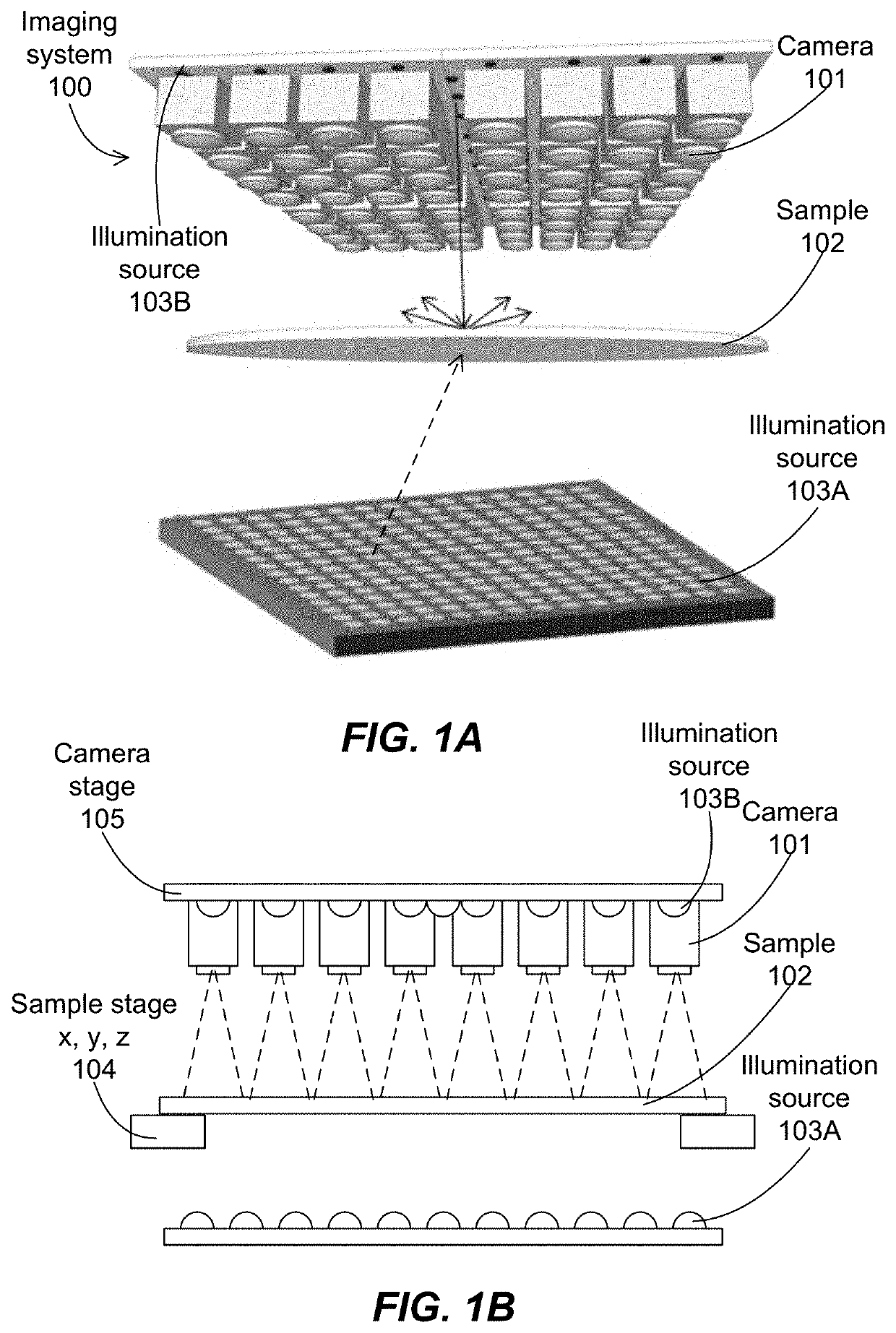
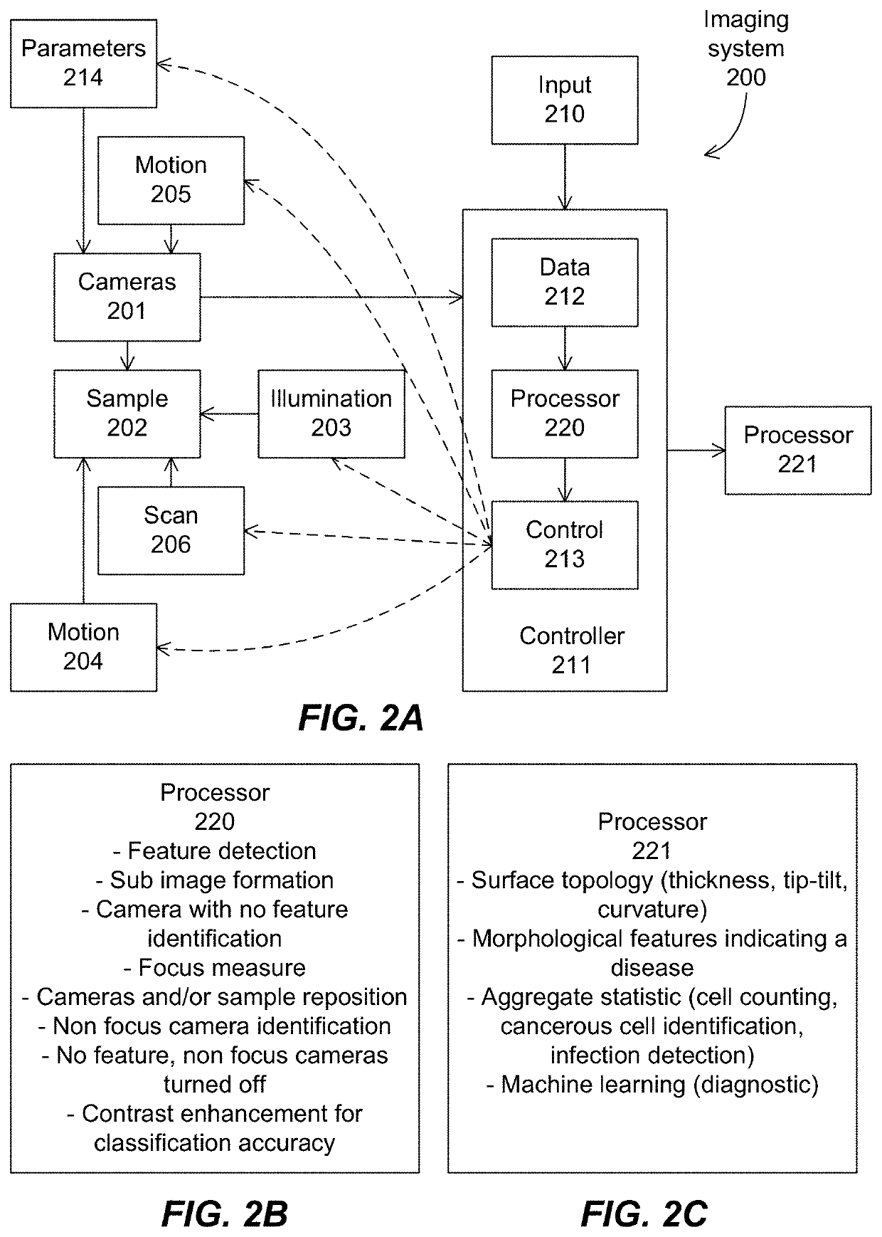
[0005]In some embodiments, the present invention discloses imaging systems and methods, that are optimized for focusing mainly on features of interest, instead of on the whole image of the sample. The imaging system can be configured to process the image captured by the multiple cameras within a camera array of the imaging system, and to communicate with a moving mechanism of the imaging system for refocusing the multiple cameras on the sample to bring into focus a maximum amount of detected features of interest on the images.

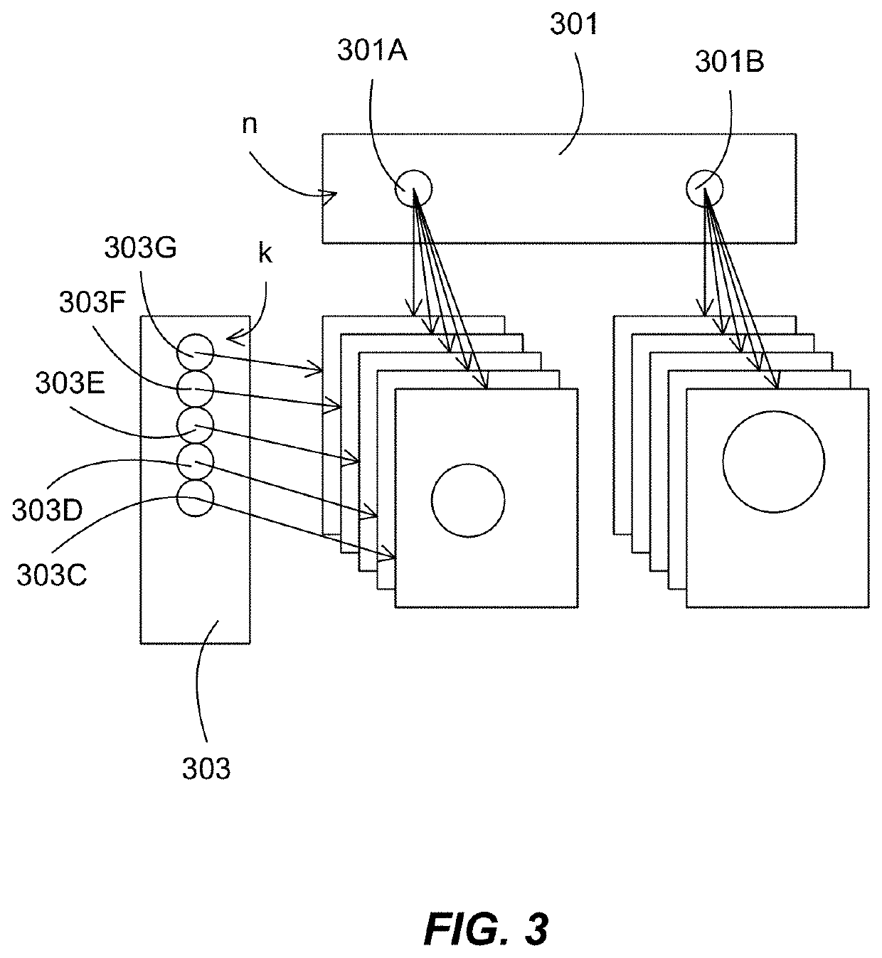
[0006]The focused areas of the detected features can be a small subset of the image data captured by the imaging system, e.g., a large percentage of the image data, which does not or which contain only few features of interest, can be out of focus. By optimizing the focus on the feature of interest, a clearer and more detailed classification of the sample can be made, which can allow a more accurate diagnostic analysis. In addition, the out-of-focus areas and t...


PUM


Abstract

An imaging system is configured with an autofocus operation that refocuses multiple cameras of the imaging system on detected features of interest, instead of on the whole image of the sample. Focus measures are calculated on the detected features, and then aggregated to focus distances of actuator moving the camera array, the sample stage, or individual cameras based on a maximization of detected features to be in focus. After the refocus, the imaging system recaptures new images and analyzes features on the new images to generate statistical characterization of the sample based on the classification of the features.

Description

[0001]The present patent application claims priority from U.S. Provisional Patent Application Ser. No. 63 / 123,049, filing date Dec. 9, 2020, hereby incorporated by reference in its entirety.BACKGROUND OF THE INVENTION[0002]Imaging thin specimens at high resolution over a large area is a notoriously challenging problem. First, it is challenging to design lenses that can see over more than a few square millimeters at less than 1 μm two-point resolution, which is the generally desirable resolution for many biological applications. Current microscope lenses are limited to capture approximately 50 megapixels per snapshot, a limitation that is primarily caused by the challenges associated with lens design. This is equivalent to imaging an approximately 3.5×3.5 mm area at 1 μm two-point resolution.[0003]To increase the area over which it is possible to capture image data at a desired resolution into the multi-centimeter regime, a straightforward idea is to scan the sample or the imaging sy...

Claims


Application Information

Patent Timeline
IPC IPC(8): G02B21/36G02B21/06H04N5/232
CPCG02B21/367G02B21/368H04N5/23212G02B21/06H01L27/14618G02B21/362G02B26/08H04N23/56H04N23/673H04N23/951H04N23/90H04N23/67
Inventor HARFOUCHE, MARKHORSTMEYER, GREGORHORSTMEYER, ROBERT
Owner RAMONA OPTICS INC
Learn More