
Component monitoring system with monitory latch assembly

a monitoring system and latch assembly technology, applied in the direction of protective switch details, force measurement by elastic gauge deformation, instruments, etc., can solve the problems of wear and tear of the components of the operating mechanism

Active Publication Date: 2017-02-16
EATON INTELLIGENT POWER LIMITED
View PDF1 Cites 32 Cited by
  • Summary
  • Abstract
  • Description
  • Claims
  • Application Information

AI Technical Summary

Benefits of technology

The patent text describes a monitoring latch assembly for a circuit breaker assembly that can measure the characteristics of its components. This data is compared to standard values to determine if the components are functioning properly. The latch assembly includes a latch member and a sensor assembly, which is placed in a pocket on the latch member. This system allows for effective monitoring of circuit breaker assembly components and can improve the efficiency of maintenance and repair efforts.

Problems solved by technology

The components of the operating mechanism are subject to wear and tear over time.

Method used


Image

  • Component monitoring system with monitory latch assembly
  • Component monitoring system with monitory latch assembly
  • Component monitoring system with monitory latch assembly

Examples


Embodiment Construction

[0035]It will be appreciated that the specific elements illustrated in the figures herein and described in the following specification are simply exemplary embodiments of the disclosed concept, which are provided as non-limiting examples solely for the purpose of illustration. Therefore, specific dimensions, orientations, assembly, number of components used, embodiment configurations and other physical characteristics related to the embodiments disclosed herein are not to be considered limiting on the scope of the disclosed concept.

[0036]Directional phrases used herein, such as, for example, clockwise, counterclockwise, left, right, top, bottom, upwards, downwards and derivatives thereof, relate to the orientation of the elements shown in the drawings and are not limiting upon the claims unless expressly recited therein.

[0037]As used herein, the singular form of “a,”“an,” and “the” include plural references unless the context clearly dictates otherwise.

[0038]As used herein, the stat...


PUM

PropertyMeasurementUnit
static pressureaaaaaaaaaa
forceaaaaaaaaaa
compressive forceaaaaaaaaaa

Abstract

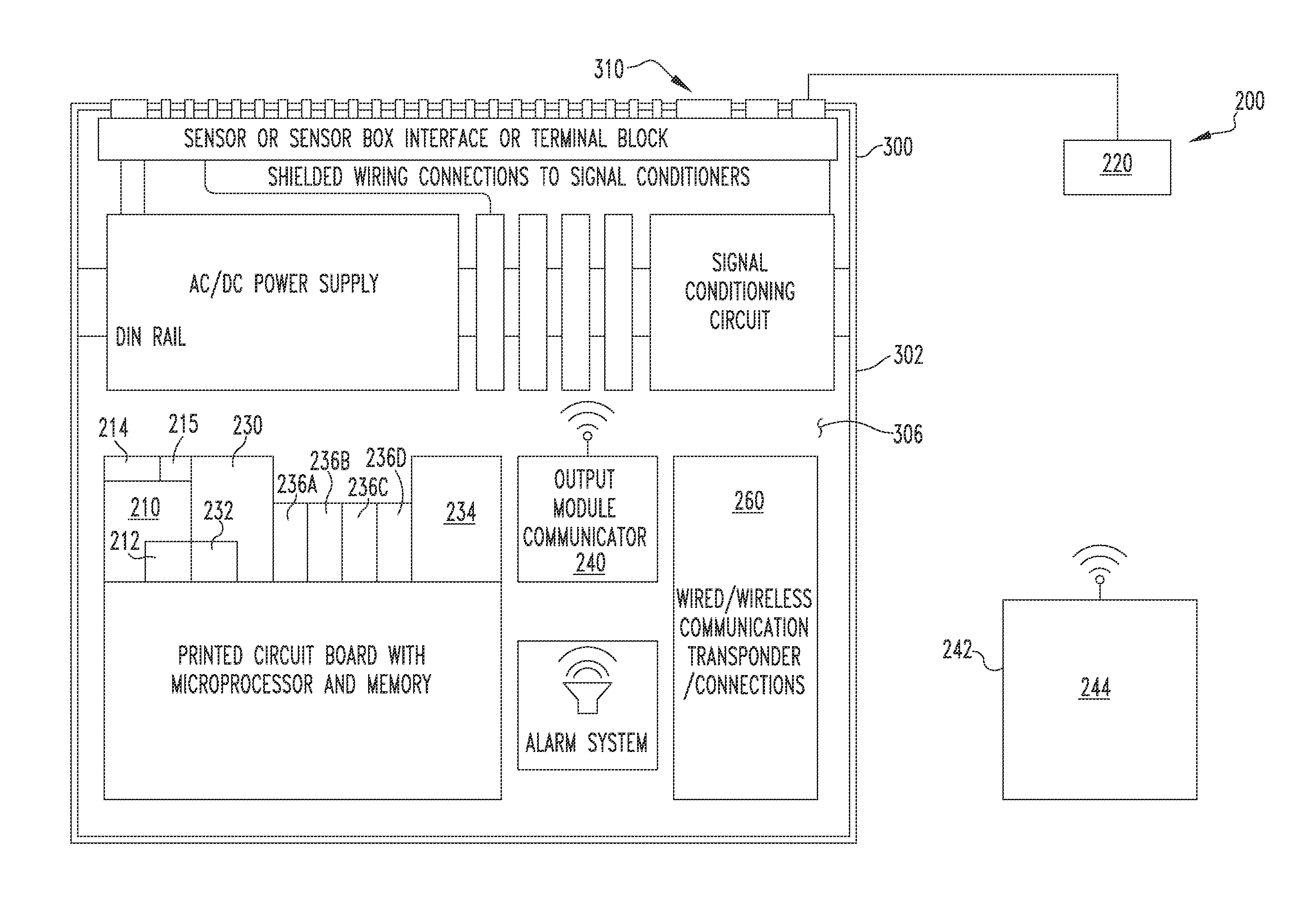
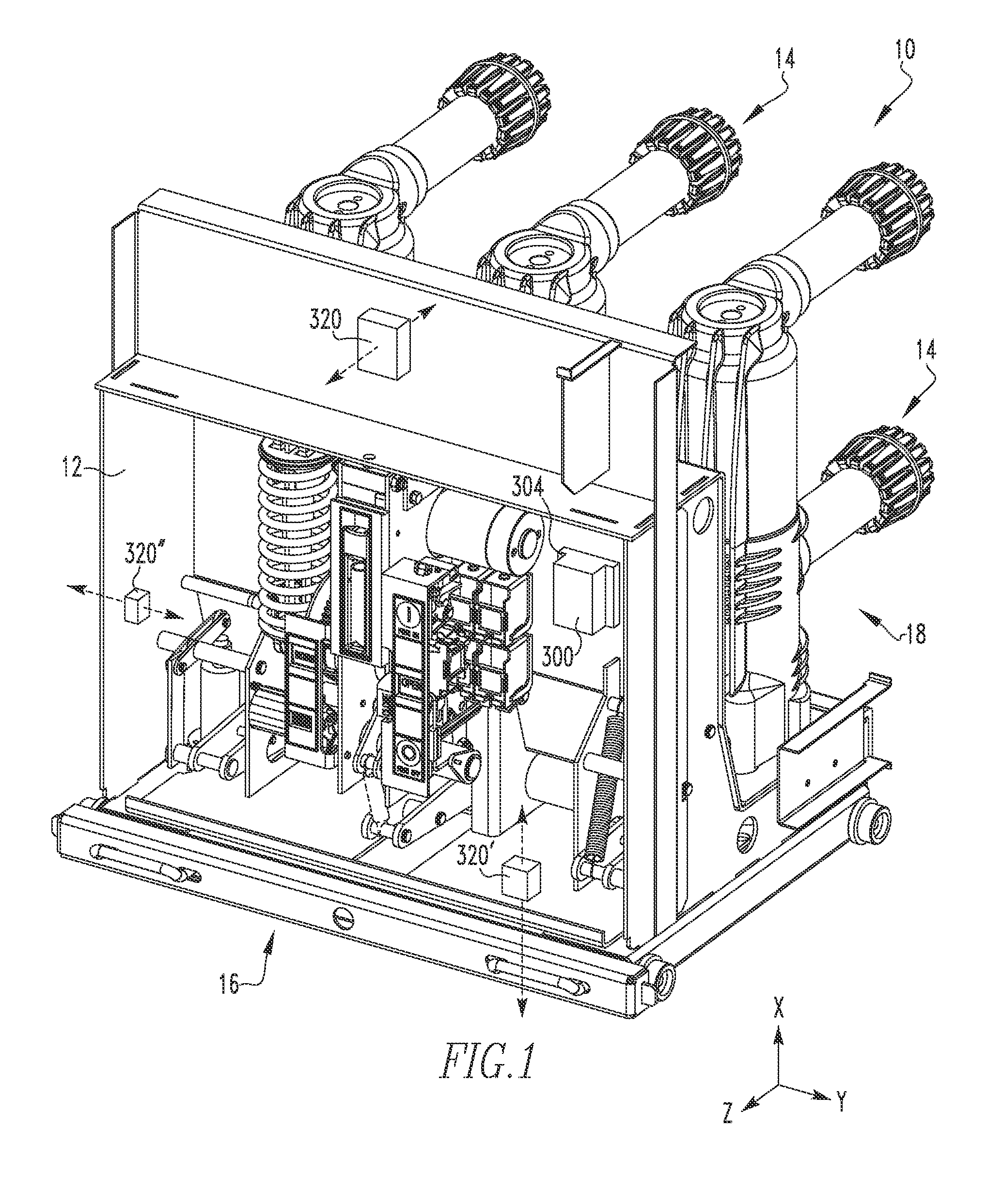
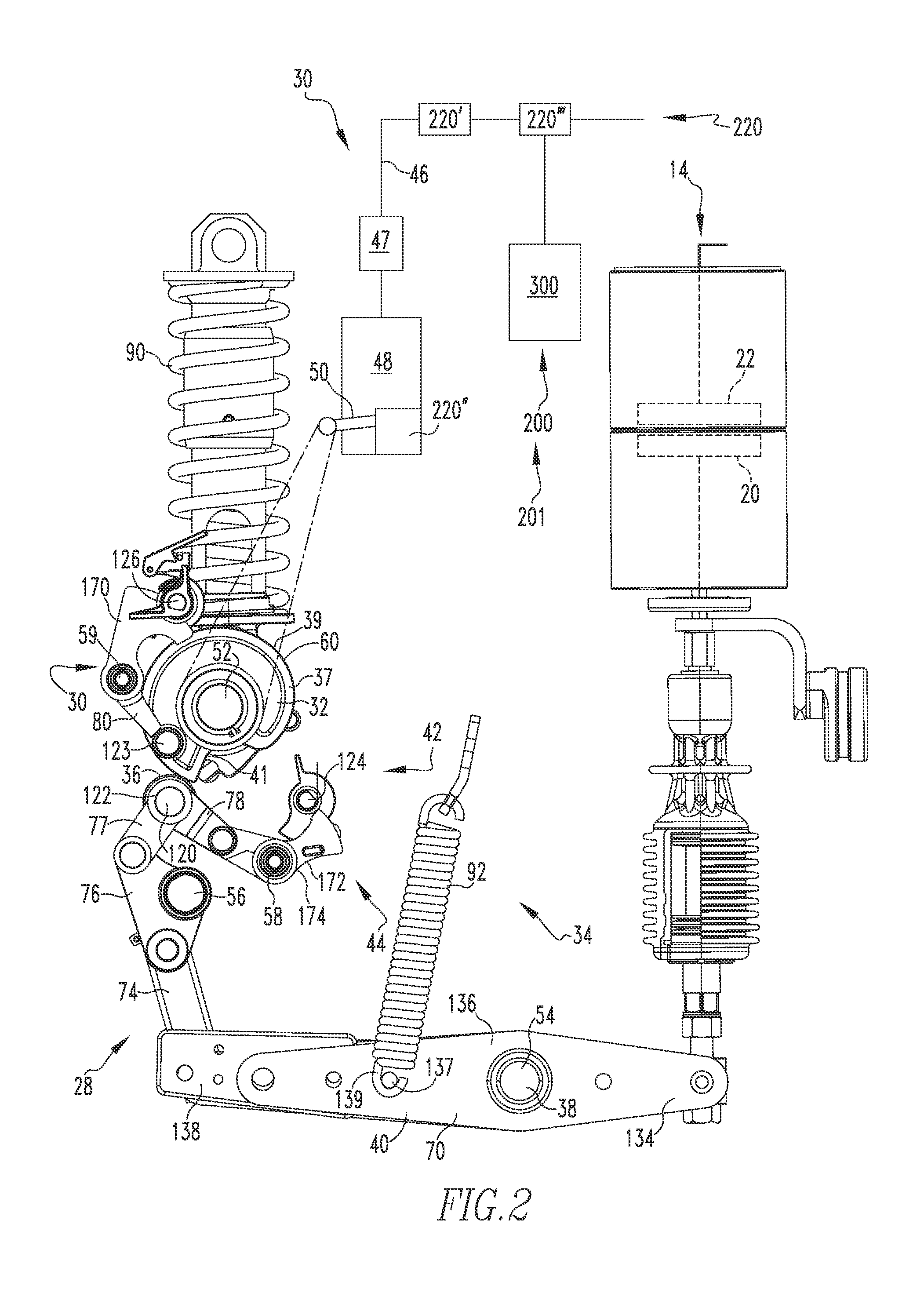
A monitoring latch assembly structured to monitor circuit breaker assembly operating mechanism component characteristics is provided. The monitoring latch assembly includes a latch member and a sensor assembly. The latch member includes a body. The latch member body defines a pocket. The sensor assembly is disposed in the latch member body pocket.

Description

BACKGROUND OF THE INVENTION[0001]Field of the Invention[0002]The disclosed and claimed concept relates to a circuit breaker with a component monitoring system and, more specifically, to a circuit breaker with a component monitoring system utilizing a monitoring latch assembly.[0003]Background Information[0004]Circuit breaker assemblies provide protection for electrical systems from electrical fault conditions such as current overloads, short circuits, and low level voltage conditions. Typically, circuit breakers include a trip device and an operating mechanism. The trip device detects an over-current condition and actuates the operating mechanism. The operating mechanism open and closes, either manually or in response to the trip device, a number of electrical contacts. In an exemplary embodiment, the operating mechanism utilizes a number of springs to generate force for the opening and closing operations. Further, the springs are maintained in a charged state so that, for example, ...

Claims


Application Information

Patent Timeline
Patent Type & Authority Applications(United States)
IPC IPC(8): H01H71/12G01R31/327G01L1/04
CPCH01H71/12G01R31/3271G01L1/04G01R31/3277H01H71/04H01H2071/046H01H2071/044H01H11/0062H01H33/42H01H33/666H01H2300/052G01R31/3275
Inventor CHEN, JIONGYU, LIWU, FANGJIMAO, BINHUICHEN, STEVEN ZHENGHONGLIU, JINGXUAN
Owner EATON INTELLIGENT POWER LIMITED
Learn More