
Soft serve dispenser

a dispenser and soft-serve technology, applied in the field of soft-serve dispensers, can solve the problems of small amount of product inside at any time, and achieve the effects of convenient dispensing, easy purging, and reduced was

Inactive Publication Date: 2017-02-23
WELDY ROSS
View PDF6 Cites 5 Cited by
  • Summary
  • Abstract
  • Description
  • Claims
  • Application Information

AI Technical Summary

Benefits of technology

The device described in this patent helps to dispense frozen products using a pump that has two screws inside it. These screws rotate in opposite directions and continuously scrape off the frozen product from the inside wall of the pump. This means that the amount of product dispensed can be easily controlled by controlling the rotation of the screws. The design also helps to minimize waste because any leftover product can be easily purged.

Problems solved by technology

Also because the inside available space is mostly consumed by the rotating screws, only a very small amount of product remains inside at any point in time.

Method used


Image

  • Soft serve dispenser
  • Soft serve dispenser
  • Soft serve dispenser

Examples


Embodiment Construction

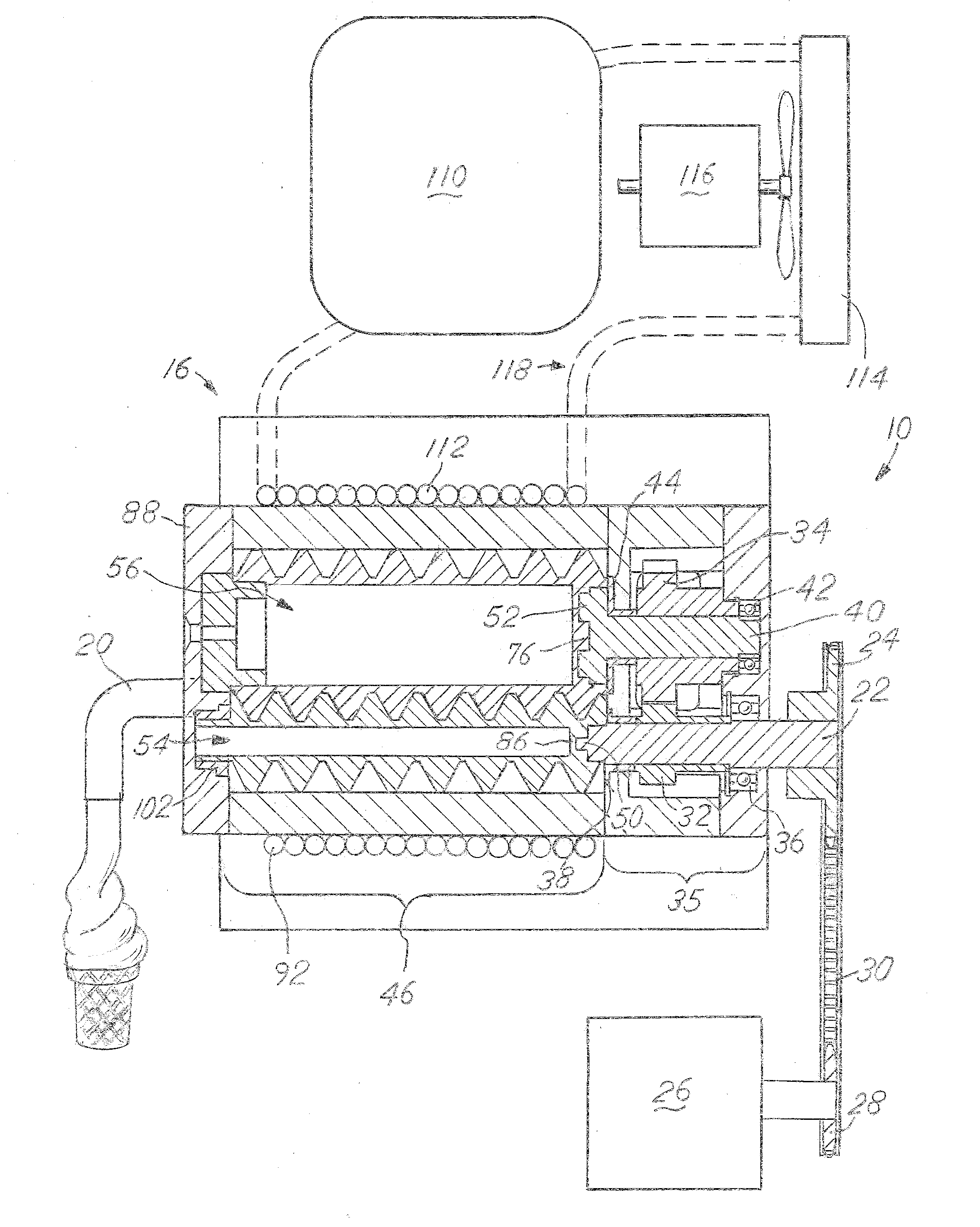
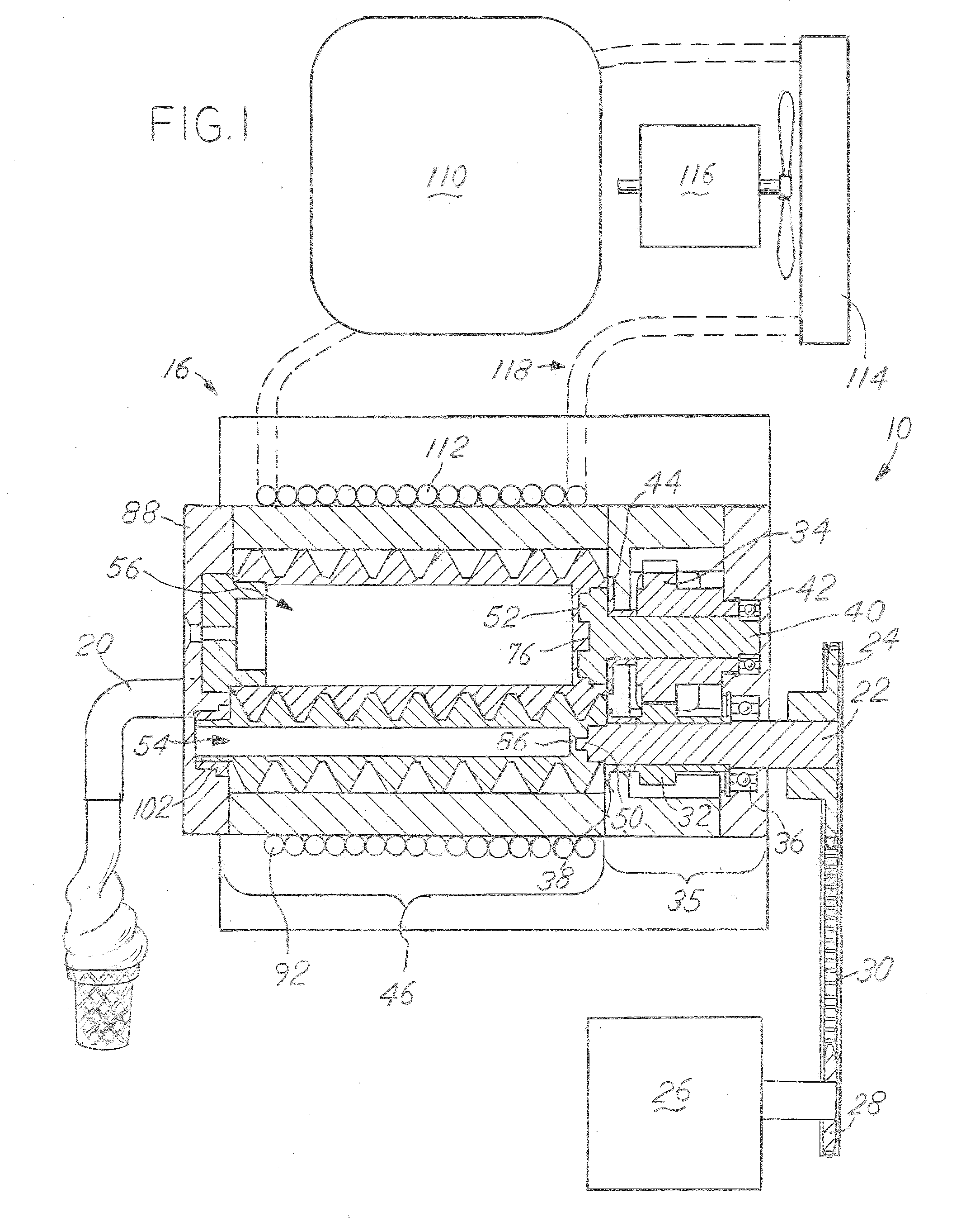
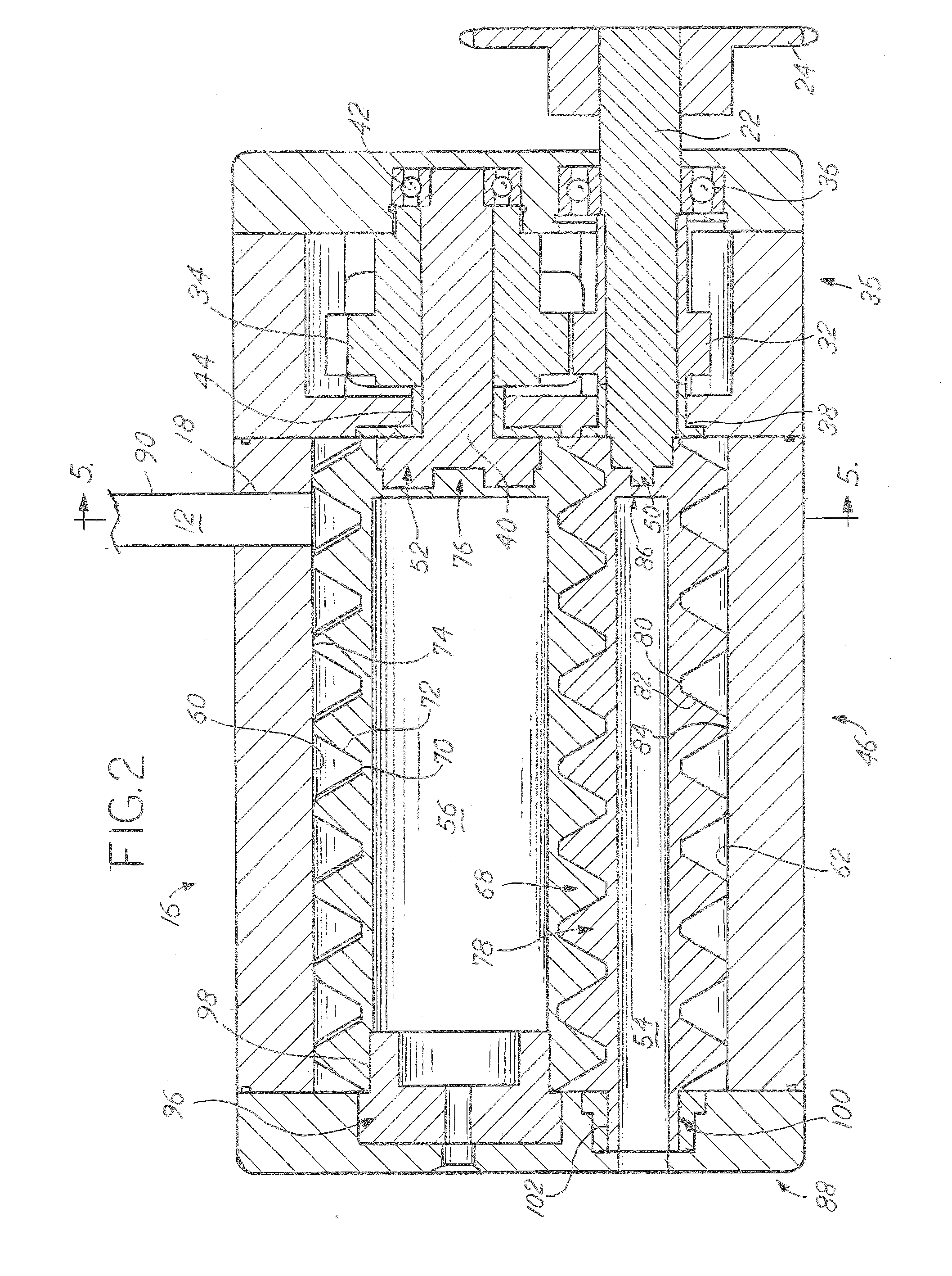
[0010]A positive displacement dispensing device 10 is shown in FIG. 1 that cools a liquid 12, FIG. 2 into a frozen product 14, such as ice cream or frozen yogurt. As shown in FIG. 2, the device has a housing 16 with an inlet port 18 and an outlet port 20FIG. 1.

[0011]At the rear of the housing 16 is an input shaft 22 with a driven sprocket 24. A motor 26 with a driving sprocket 28, FIG. 1 as shown in FIG. 1 connected to the driven sprocket 24 by a chain 30 transfers power to the input shaft 22. A keyway and key secures the driven sprocket 24 to the input shaft 22. It is contemplated that the input shaft 22 is driven directly by the motor 26.

[0012]Mounted to the input shaft 22 is a driving gear 32, FIG. 2 that meshes with a driven gear 34. The gears 32, 34 are located in the gear portion 35 of the housing 16. Supporting the shaft 22 on the end closest to the driven sprocket 24 is a bearing 36. As shown in FIG. 2, it is a ball bearing, but it could be any other type of device such as a...


PUM


Abstract

A positive displacement chilled food dispenser is provided where liquid enters a portion of a housing where two screws reside. The housing is chilled below the freezing temperature of the liquid. The two screws, when rotating, move the liquid towards a dispensing end. The liquid freezes where it contacts the housing and is scraped by an outside diameter of the two screws. The frozen liquid is then dispensed through a dispensing end. At the dispensing end is an optional valve that selectively shuts the flow of frozen liquid off. Alternatively, a sensor determines how much frozen liquid is dispensed through the dispensing end.

Description

BACKGROUND OF THE INVENTION[0001]Frozen treats such as ice cream, frozen yogurt, and the like have been a mainstay for people wanting to refresh themselves after a hot day, a meal, or just for a snack. Commonly, soft-serve ice cream or frozen yogurt is dispensed from a machine that both freezes a liquid into a flowable solid then dispenses it. In the current art, the machines use a spiral auger having a single straight blade that scrapes frozen product from the inside diameter of the dispensing cavity. The system has remained largely unchanged for many years and functions, except for the hassle and waste generated by cleaning and the inability to automatically dispense metered amounts. Currently in the art, a large cavity of unused product remains and must be discarded at the end of the day or when a flavor changeover is desired. An improved frozen treat dispenser is needed.SUMMARY OF THE INVENTION[0002]The present disclosure describes a device for dispensing a metered amount of fro...

Claims


Application Information

Patent Timeline
Patent Type & Authority Applications(United States)
IPC IPC(8): A23G9/28
CPCA23G9/281
Inventor WELDY, ROSS
Owner WELDY ROSS
Learn More