Under mattress support

a mattress and support technology, applied in the field of mattress support, can solve the problems of reducing body support and sleeping comfort, requiring new mattresses, and so on, and achieve the effect of adequate resiliency and facilitate lateral compression of the under mattress

Active Publication Date: 2017-02-23
FREN COLLEEN M
View PDF3 Cites 9 Cited by
  • Summary
  • Abstract
  • Description
  • Claims
  • Application Information

AI Technical Summary

Benefits of technology

[0014]In one general implementation, an under mattress support is provided for positioning between a box spring support and a sagging area of an overlying mattress, the box spring support and overlying mattress having corresponding sides extending longitudinally between upper and lower ends of the respective box spring and mattress ends. The under mattress support includes: (a) a series of parallel spaced-apart laterally extending elongated resilient unitary slats, each slat having a predetermined width and height and a predetermined slat length adequate to extend laterally from a portion of one of the sides of the mattress to a portion of the opposite side of the mattress; (b) a unitary bottom pliable fabric cover disposed beneath the slats such that the bottom pliable fabric cover extends completely beneath all of the slats; and (c) a top pliable fabric cover disposed above the slats such that the top pliable fabric cover extends completely above all of said slats, the top pliable fabric cover selectively fixedly attached to said bottom pliable fabric cover in a manner resulting in the permanent encasement of each of said resilient slats within a corresponding unique slat enclosure such that each individual encased slat has a contiguous exterior surface completely surrounded by, and directly adjacent to, a corresponding contiguous interior surface of the corresponding unique slat enclosure. In this manner, each unitary resilient slat is completely permanently encased within a corresponding unique enclosure rendering the slat inaccessible. Preferably, the selective attachment further includes first and second laterally-extending linear cover attachment portions each permanently affixing the top and bottom fabric cove

Problems solved by technology

Over periods of extended use, conventional mattresses tend to develop areas of sag that may develop a concave center or side area, or become too soft, greatly reducing body support and sleeping comfort.
In some cases, the degree of sagging is so great that a new mattress must be purchased.
In other cases, while the mattress may not be considered unusable it is uncomfortable and often leads to body aches due to lack of adequate support of the body in a preferred sleeping posture.
However, a crucial feature of such an under mattress support is that it adequately resolves such sagging and soft areas of the mattress without simultaneously creating a stiffer less comfortable overall mattress feel to an individual lying on the mattress.
However, conventional solutions have proven unsatisfactory for a variety of reasons.
Again, it has been well established that such use of rigid support structures, whether in the form of panels, slats and the like, creates an unnaturally stiff or rigid mattress feel that is uncomfortable to rest or sleep on, which is a significant drawback associated with these common approaches to the problem, and any related approaches that introduce rigid under mattress support structures.
Again, this type of device suffers from the same disadvantages; that is, an overly rigid uncomfortable mattress support.
This approach has resulted in very limited support by individual air-filled chambers, which has proven to be inadequate for lifting and restoring a sagging mattress to a comfortable disposition.
That is, these air chambers tend to displace, or shift the air from beneath the individual, due to the force applied by the body, to a location alongside the individual, while also creating an undesirable hardened bulge and requiring ongoing maintenance.
Some devices include foldable cardboard pieces, and some devices sit atop a mattress and are made of steel rods or other hard and rigid materials, which do not provide a comfortable support for at least the foregoing reasons.
However, such bed board st

Method used


Image

  • Under mattress support
  • Under mattress support
  • Under mattress support

Examples


Embodiment Construction

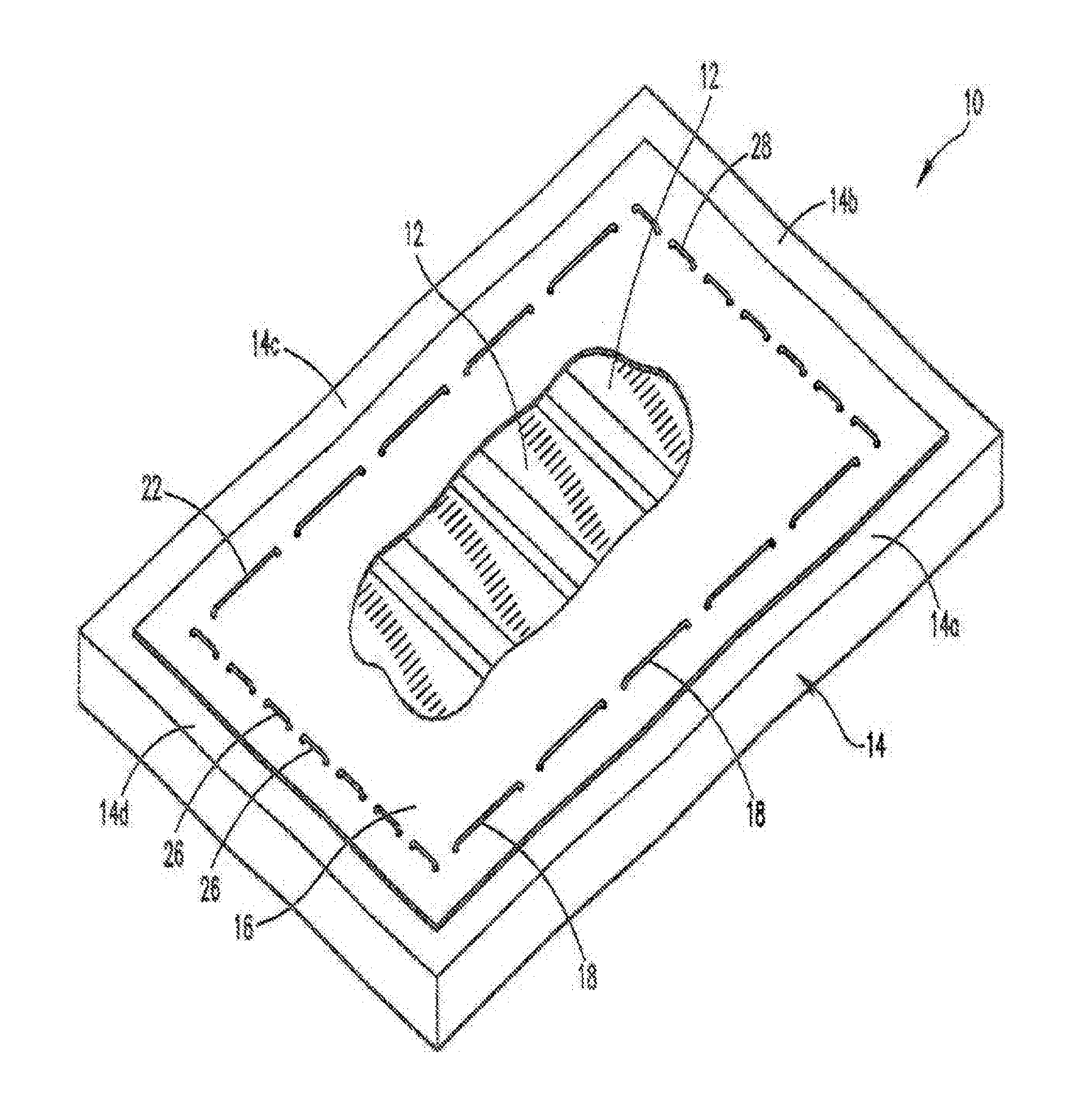
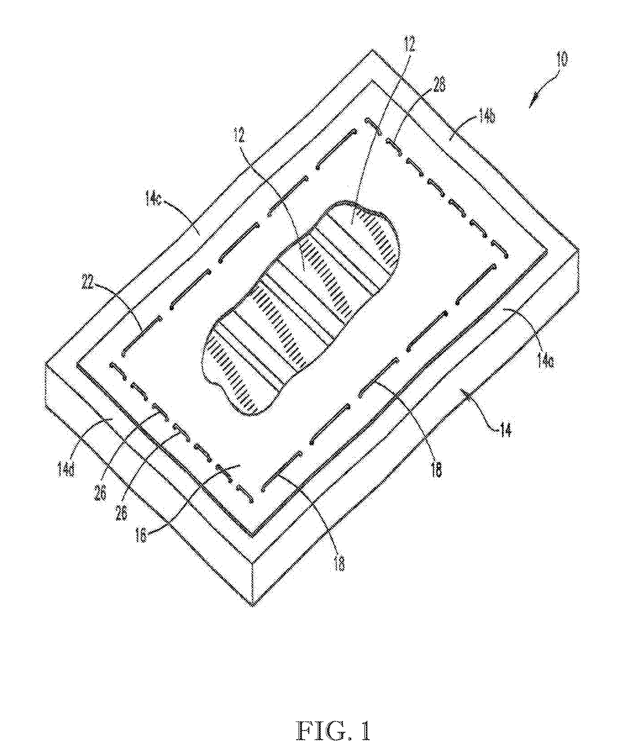
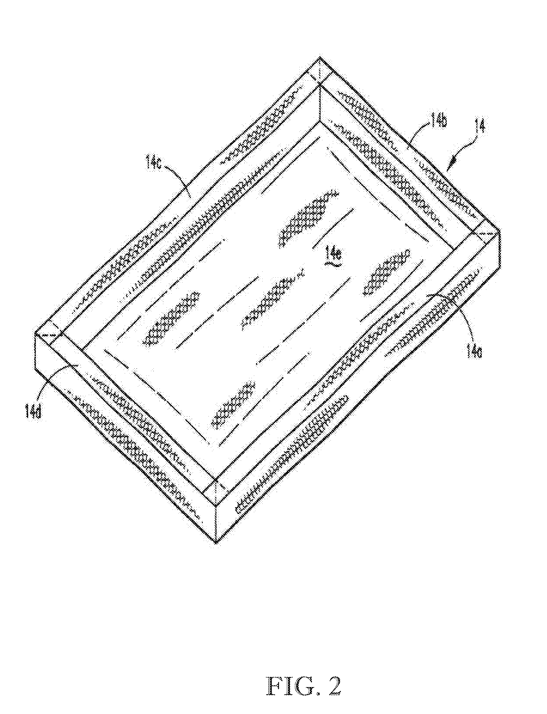
[0045]Referring now to the drawings and in particular to a first exemplary implementation of FIG. 1, the under mattress support 10 is shown. The support 10 includes an array comprising a plurality of elongated unitary resilient slats 12, such as, for example, but not limited to, elongated heavy duty polyurethane foam slats, expanded polyethylene slats; expanded polypropylene slats; expanded polyurethane slats; expanded polystyrene, rubber slats, polyethelene-styrofoam composite slats or any other resilient materials having similar characteristics, which are now known or discovered in the future and preferably capable of being easily formed into any desired geometric shape. Preferably, the slats 12 are arranged parallel to each other and spaced-apart preferably within a range of about 2 inches to 5 inches, as shown. However, the slat separation between adjacent slats can fall outside of this preferred range if required by a specific mattress or box spring construction. The lateral cr...


PUM


Abstract

An under mattress support extends the longevity of an existing mattress that may include concave areas resulting in sagging or soft areas, including a plurality of parallel oriented spaced-apart resilient elongated slat members interconnected by pliable strips to form a parallel slat array. The pliable strip spacing of the parallel resilient slats allows for lateral compression to enhance support. In use, the under mattress support is interposed between a mattress and underlying box spring such that the elongated slats extend along their longitudinal direction from a portion of one side of the mattress to the opposite side of the mattress where the concave portion of a sagging or soft mattress appears during the normal course of use.

Description

CROSS-REFERENCE TO RELATED APPLICATIONS[0001]This U.S. non-provisional utility patent application is a continuation-in-part of copending U.S. non-provisional utility patent application Ser. No. 14 / 170,776 filed on Feb. 3, 2014, which, in turn, is a continuation-in-part of U.S. non-provisional utility patent application Ser. No. 13 / 758,045 (now abandoned) filed on Feb. 4, 2013, all of which are incorporated-by-reference herein in their entireties.BACKGROUND OF THE INVENTION[0002]Field of the Invention[0003]The present invention generally relates to a mattress support for being interposed between an underlying box spring and overlying mattress, and more specifically to a portable under mattress support uniquely constructed to incorporate spaced-apart resilient slats interconnected by strips, for use to restore the support integrity to one or more sagging or otherwise softer well-used areas of a mattress.[0004]Description of Related Art[0005]Over periods of extended use, conventional m...

Claims


Application Information

Patent Timeline
IPC IPC(8): A47C21/06
CPCA47C21/06A47C19/027A47C20/027A47C27/087A47C31/123
Inventor FRANKEN, COLLEEN M.
Owner FREN COLLEEN M
Why Eureka
Try Eureka