

Operation knob and display device in which same is used
a technology of operation knob and display device, which is applied in the direction of mechanical control device, process and machine control, instruments, etc., can solve the problems of degradation of operation, and achieve the effect of improving the operationability and durability of the operation knob according to the present invention
- Summary
- Abstract
- Description
- Claims
- Application Information
AI Technical Summary
Benefits of technology
Problems solved by technology
Method used
Image

Examples
first exemplary embodiment
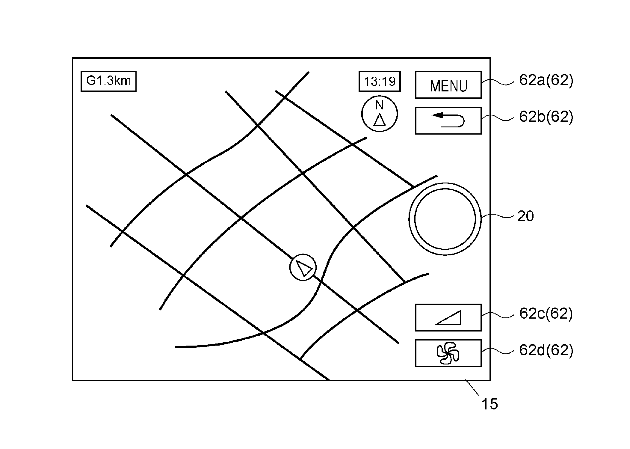
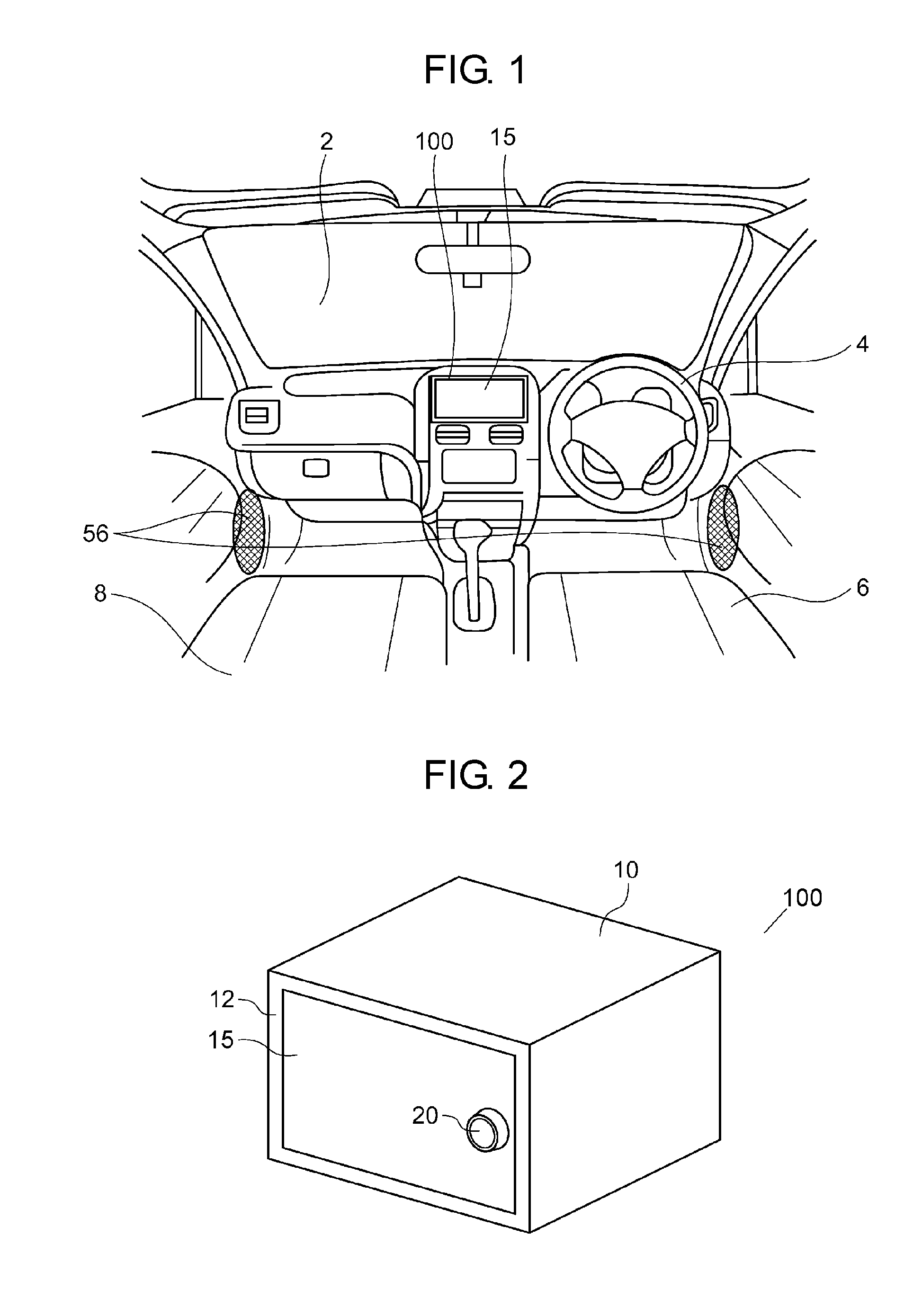
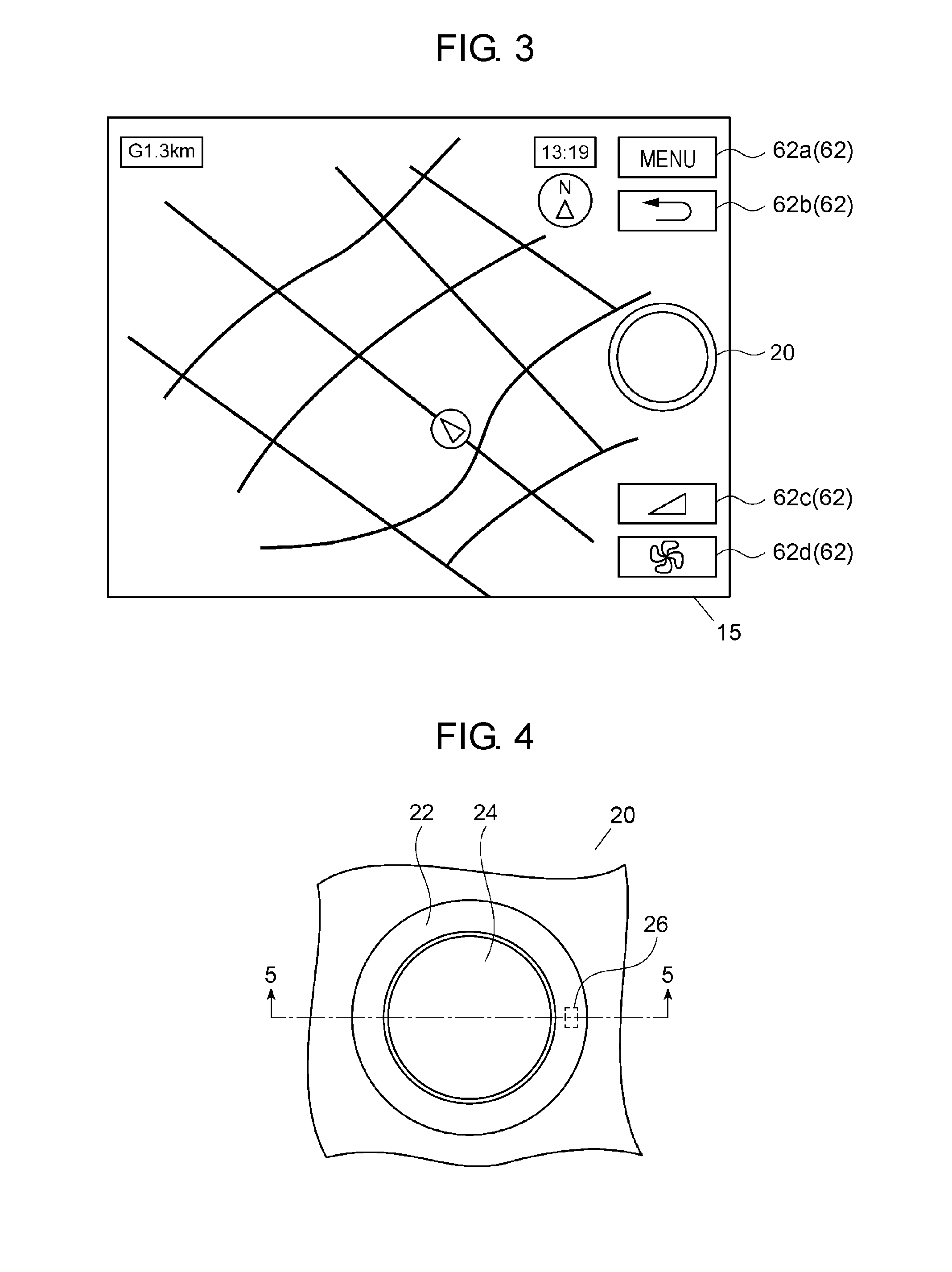
[0047]A first exemplary embodiment of the present invention relates to a display device including an operation knob attached onto a touch functional display panel. An example of the display device is an on-board device, such as a car audio device and a car navigation device. It is effective to attach the operating knob onto the touch functional display panel in order to improve operability of the touch functional display panel.
[0048]However, when a rotating operation to the operation knob as shown in PTL 1 is repeated, a part of the operation knob continues to rotate while contacting the touch functional display panel. This rotation may damage the touch functional display panel. Accordingly, the exterior of the touch functional display panel is damaged, and the durability of the touch functional display panel is degraded. In addition, a part of the operation knob contacting the touch functional display panel is worn, and the operation knob may not preferably contact the touch functi...
second exemplary embodiment
[0106]Operation knob 1020 according to a second exemplary embodiment will be described below with reference to FIG. 13 and FIG. 14. FIG. 13 is a front view of operation knob 1020 according to the present embodiment. FIG. 14 is a sectional view of the operation knob along line 14-14 illustrated in FIG. 13. Operation knob 1020 is attached onto panel 15 of display device 100 illustrated in FIG. 2, similarly to operation knob 20 in accordance with the first embodiment. A through-hole is provided in button type operation unit 1024 of operation knob 1020. Light guiding unit 1094 that transmits light from panel 15 is disposed in the through-hole. The same configurations as in the first exemplary embodiment will be denoted by the same reference signs and will not be detailed.
[0107]When it becomes dark around display device 100 illustrated in FIG. 1 and FIG. 2, visibility of an operation knob is degraded. When the visibility is degraded, the operability of the operation knob is affected adve...
third exemplary embodiment
[0147]Operation knob 2020 according to a third exemplary embodiment will be described with reference to FIG. 20 and FIG. 21. FIG. 20 is a front view of operation knob 2020 according to the present embodiment. FIG. 21 is a sectional view of the knob along line 21-21 illustrated in FIG. 20. Operation knob 2020 is attached onto panel 15 of display device 100 illustrated in FIG. 2, similarly to operation knob 20 in accordance with the first embodiment. Separating unit 2096 is disposed between operation surface 2022A of dial type operation unit 2022 and operation surface 2088A of button type operation unit 2024 of operation knob 2020. Dial type operation unit 2022 and button type operation unit 2024 are made of conductive material while separating unit 2096 is made of non-conductive material. The same configurations as in the first embodiment will be denoted by the same reference signs and may not be described in detail.
[0148]Each of some operation knobs in accordance with the first and ...
PUM
 Abstract
Description
Claims
Application Information