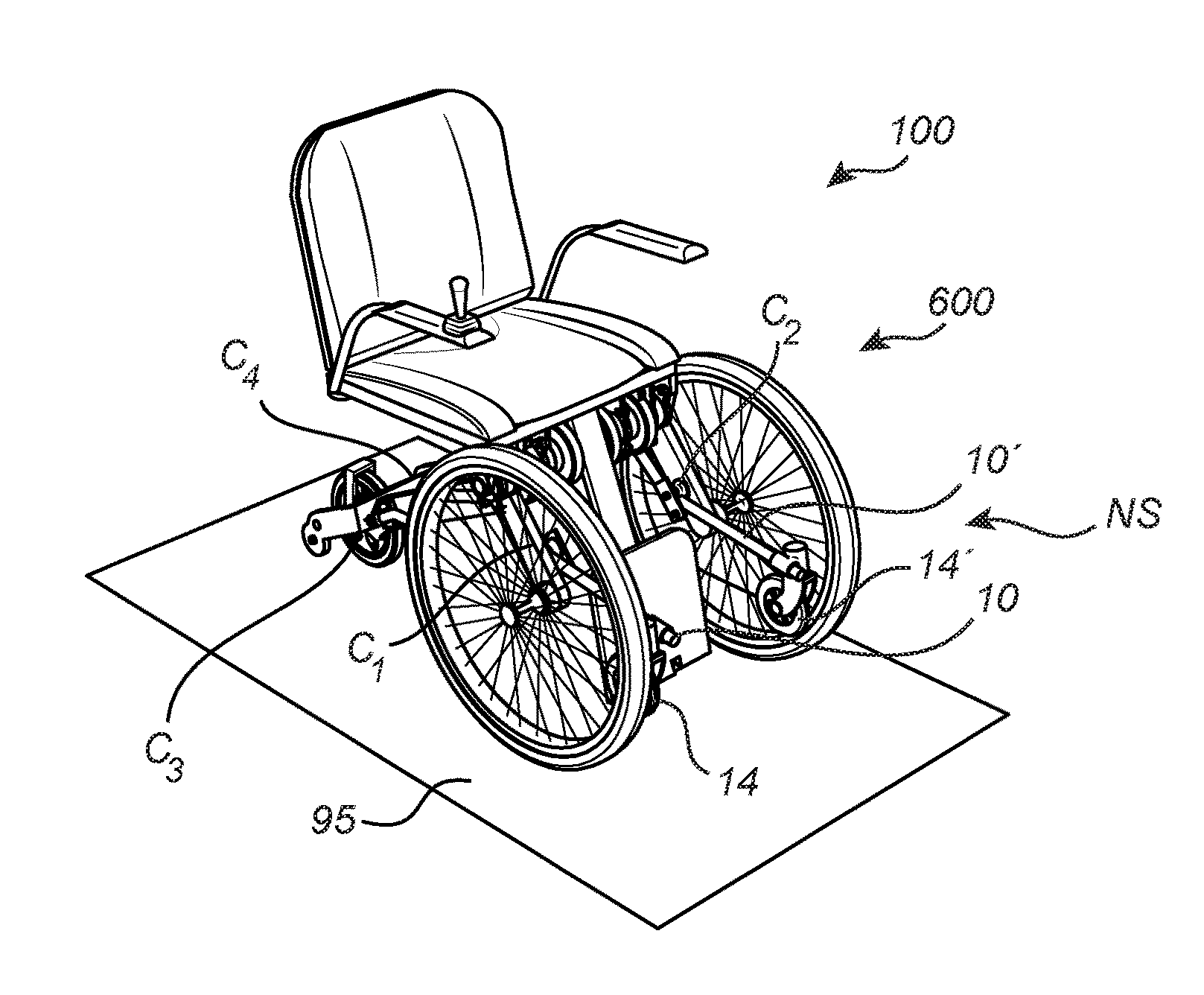
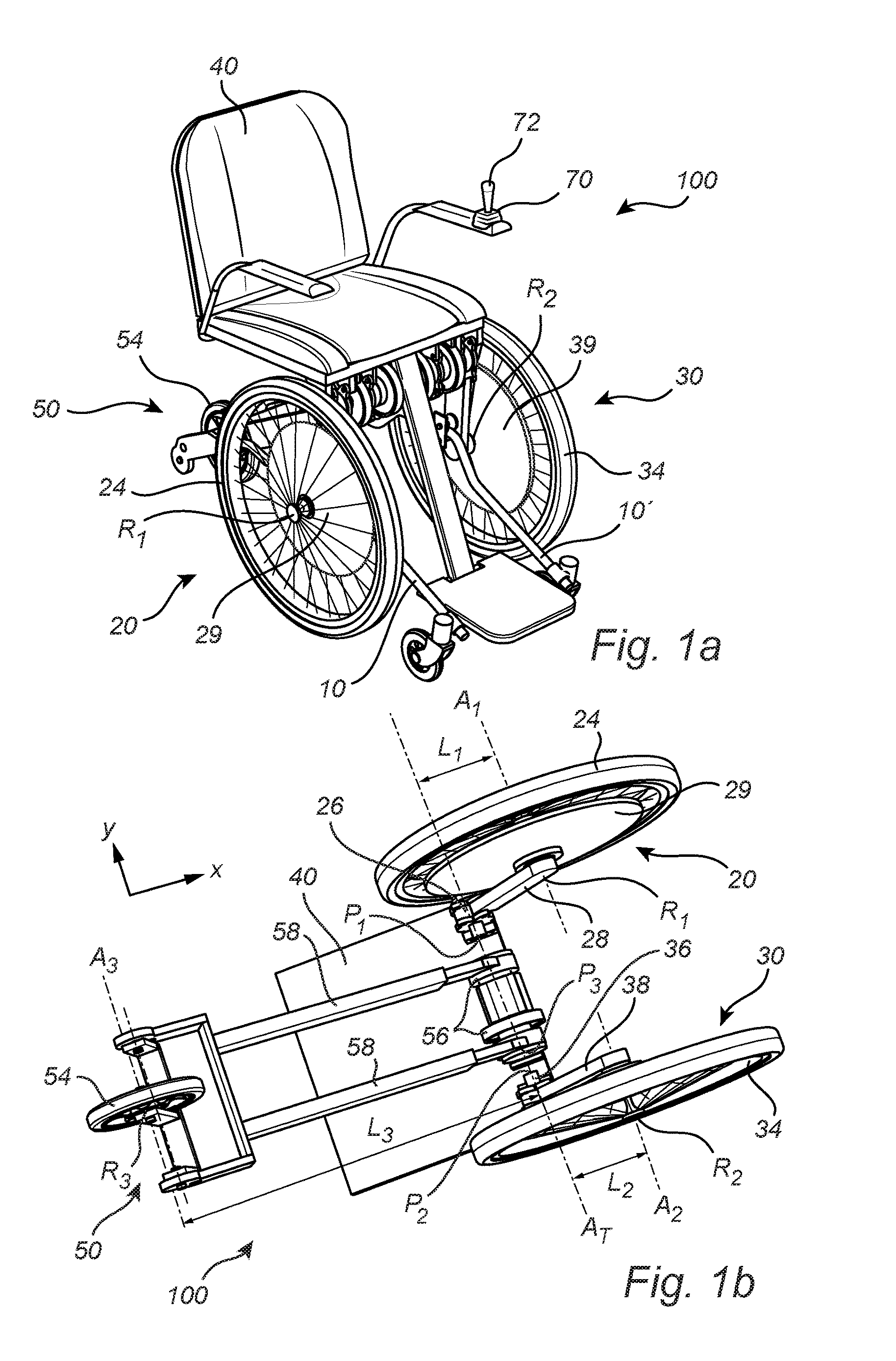
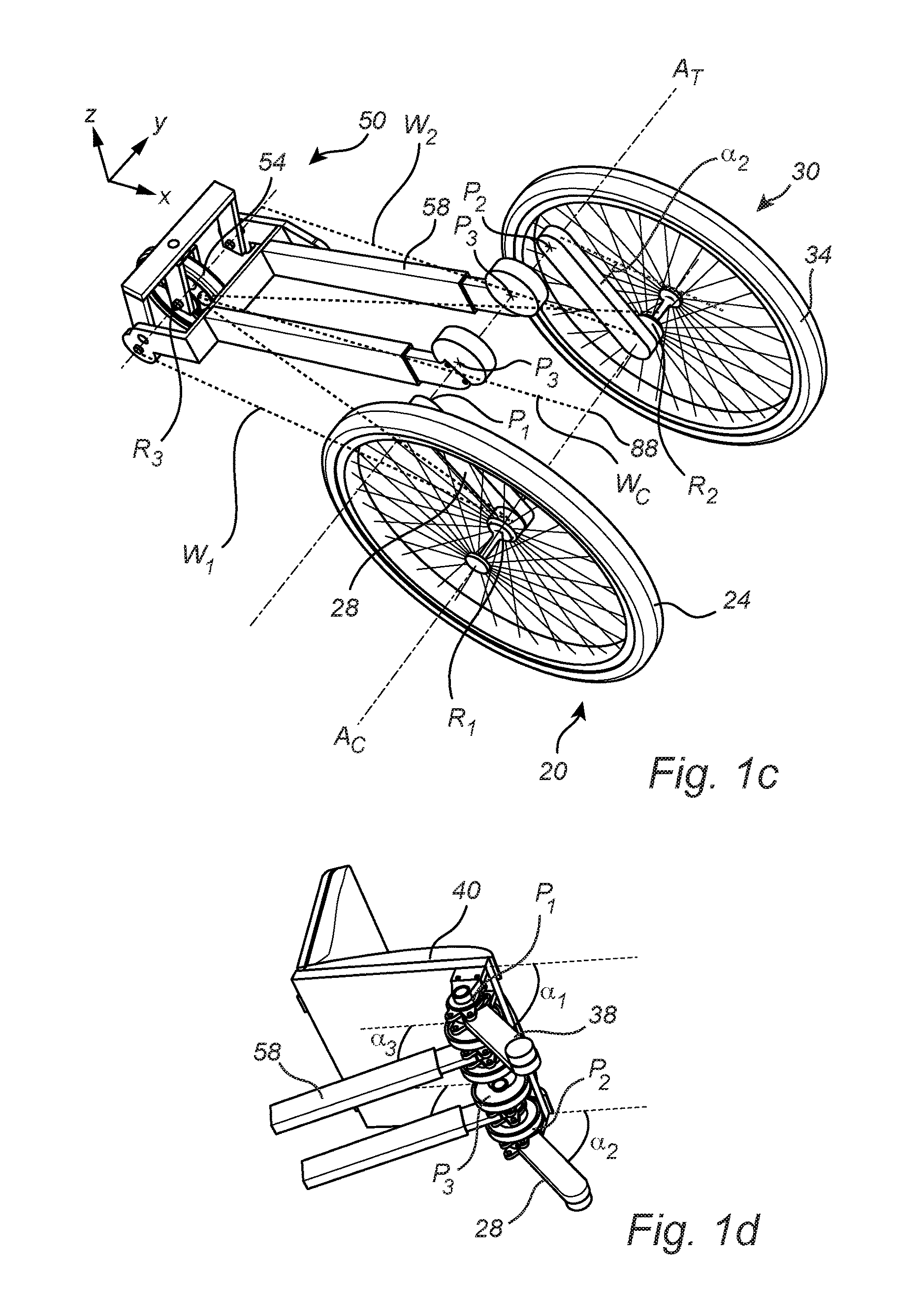
Powered wheelchair

Inactive Publication Date: 2017-03-02
REAC
View PDF0 Cites 5 Cited by
  • Summary
  • Abstract
  • Description
  • Claims
  • Application Information

AI Technical Summary

Benefits of technology

[0048]By means of the rotation mechanism, as mentioned above, it becomes possible to provide a powered wheelchair that is capable of transforming shape and wheelbase upon a rotation of any one of the rotation mechanisms. More specifically, due to the arrangement that each one of the main wheel assemblies is separately connected to corresponding rotation mechanisms, it becomes possible to independently operate each one of the wheel assemblies in order to adjust the wheelbase of the powered wheelchair. To this end, the powered wheelchair is capable of providing an improved control function while enabling a transformation between various operational modes that alleviates the drawbacks of many conventional powered wheelchairs.
[0049]In addition, since the pair of opposing main wheel assemblies and the third main wheel assembly are connected to the seat frame, it becomes possible to adjust the position of the seat frame by adjusting the position of any one of the wheel assemblies. The position of a main wheel assembly is adjusted by pivoting the main wheel assembly about its corresponding piv

Problems solved by technology

Yet, some anti-tip supports or anti-tip support wheels may be regarded as i

Method used


Image

  • Powered wheelchair
  • Powered wheelchair
  • Powered wheelchair

Examples


Embodiment Construction

[0081]The present invention will now be described more fully hereinafter with reference to the accompanying drawings, in which currently preferred embodiments of the invention are shown. This invention may, however, be embodied in many different forms and should not be construed as limited to the embodiments set forth herein; rather, these embodiments are provided for thoroughness and completeness, and fully convey the scope of the invention to the skilled addressee. Like reference characters refer to like elements throughout. Note that the directions in the following description are used for facilitating the understanding of a positional relation between components in the figures and that the directions may be different in other driving directions of the powered wheelchair. The same is applied to other exemplary embodiments described below.

[0082]Although the following description has been made to an electric-powered wheelchair, the present inventive concept may as well be implement...


PUM


Abstract

The invention relates to a powered wheelchair (100) for transporting a person, comprising a seat frame (40) for supporting the person, a pair of opposing main wheel assemblies (20, 30), including a first main wheel assembly (20) and a second main wheel assembly (30) connected to the seat frame (40), and a third main wheel assembly (50) arranged spaced apart from the pair of opposing main wheel assemblies (20, 30) and connected to said seat frame (40). The powered wheelchair further comprises a support wheel arrangement (10) for supporting the powered wheelchair (100), said support wheel arrangement (10) having a main beam (12) and a front support wheel unit (14) capable of being applied to a ground surface (95). The main beam (12) is rotatably connected to said third main wheel assembly (50) at a third connection point (C3) and connected via a guiding mechanism (80) to the first main wheel assembly (20) at a first connection point (C1). The main beam (12) has a first portion (16) adapted to cooperate with said guiding mechanism (80) when said first portion (16) passes through a part of the guiding mechanism (80) upon movement of the main beam (12) relative to the guiding mechanism (80), to maintain said support wheel arrangement in a supporting position (S), in which the front support wheel unit is applied to the ground surface (95).

Description

FIELD OF THE INVENTION[0001]The invention relates to a powered wheelchair for transporting a person. Although the invention will be described in relation to an electric-powered wheelchair, the invention is not restricted to a wheelchair having this particular power source, but may also be used in other types of powered wheelchairs and / or power-assisted wheelchair.BACKGROUND OF THE INVENTION[0002]Wheelchairs are important devices for people suffering from conditions which reduce their capability to walk, for example as a result of illness, injury, or disability. A wheelchair may increase the quality of life for millions of people suffering from such conditions.[0003]More recently, powered wheelchairs have become a more common solution for facilitating motion for affected persons, in particular persons suffering from more severe conditions. One type of powered wheelchairs is an electrically powered wheelchair. The power to an electrically powered wheelchair can for instance be provide...

Claims


Application Information

Patent Timeline
IPC IPC(8): A61G5/04A61G5/06A61G5/10A61G5/12
CPCA61G5/042A61G5/128A61G2203/14A61G5/1089A61G5/1056A61G5/06A61G5/1086A61G2203/42
Inventor OLSSON, CARL JOHAN
Owner REAC
Why Eureka
Try Eureka