Power sharing solid-state relay

a solid-state relay and power sharing technology, applied in the field of solid-state relays, can solve the problems of reducing battery life, requiring constant charge on the control gate, and no robust supply path on the secondary sid

Active Publication Date: 2016-02-04
TRIUNE IP
View PDF11 Cites 19 Cited by
  • Summary
  • Abstract
  • Description
  • Claims
  • Application Information

AI Technical Summary

Benefits of technology

[0016]FIG. 9 is a diagram of a system that provides additional control functionality within the solid-state relay; and
[0017]FIG. 10 is a diagram of an automotive control circuit in accordance with an exemplary embodiment of the present disclosure.

Problems solved by technology

One of the challenges with solid state relays is that they require a constant charge on the control gate.
As such, this constraint requires the control circuit to be constantly operating, which can reduce the battery life when the control circuit is a portable device, as is often the case when a separate power source is not provided for the control circuit.
Because there is no ground line, there is no robust supply path on the secondary side.
This continued clocking consumes continuous power from the primary side.
In many cases, the primary side is battery powered, and therefore, the battery power is consumed.

Method used


Image

  • Power sharing solid-state relay
  • Power sharing solid-state relay
  • Power sharing solid-state relay

Examples


Embodiment Construction

[0018]In the description that follows, like parts are marked throughout the specification and drawings with the same reference numerals. The drawing figures might not be to scale and certain components can be shown in generalized or schematic form and identified by commercial designations in the interest of clarity and conciseness.

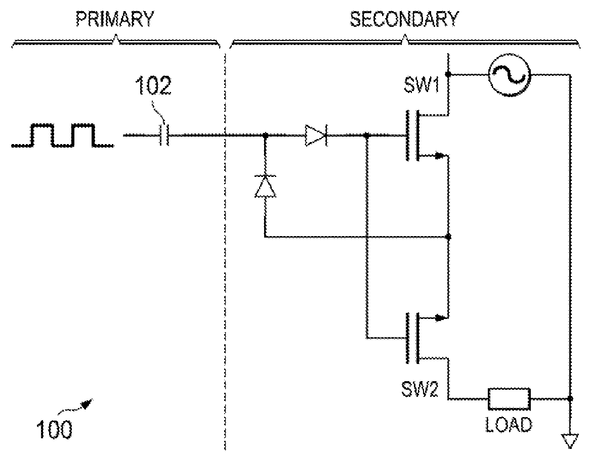
[0019]Referring to FIG. 1, it would be more desirable to be able to latch the solid state relay 100 on and not to continuously provide a clock signal. This configuration would allow the primary side control system to save power.

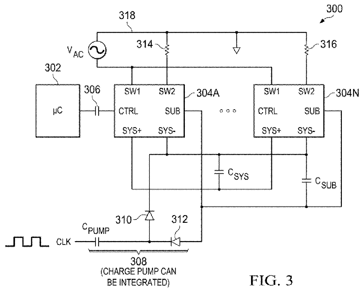
[0020]Solid-state relays can be used for driving 24 VAC systems, including but not limited to HVAC control systems, security systems, smoke detector systems, water sprinkler control systems and pool control systems. These systems can be configured to use isolated and non-isolated power systems. Because there is no supply and ground line located at the secondary side of the solid state relay, energy can be alternatively received by r...


PUM


Abstract

A solid-state switch, comprising at least one switch controller. At least one switch having a first terminal coupled to a power source, a second terminal coupled to the power source and a control terminal coupled to the switch controller and configured to selectively conduct and block current flow from the first terminal to the second terminal. At least one power converter coupled to the first terminal and the second terminal and configured to convert power from the power source from a first voltage level to a second voltage level and to provide power at the second voltage level to the switch controller.

Description

RELATED APPLICATIONS[0001]The present application claims priority to U.S. Provisional Patent Application No. 62 / 031,066, filed Jul. 30, 2014, which is hereby incorporated by reference for all purposes as if set forth herein in its entirety.TECHNICAL FIELD[0002]The present disclosure relates generally to solid state relays, and more specifically to biasing and redirecting energy in a solid state relay to provide power to other relays, as well as to redirect and balance energy across an isolated or non-isolated secondary region to the primary region.BACKGROUND OF THE INVENTION[0003]Solid state relays provide a more reliable and faster means to switch loads on and off in a secondary region. When compared to mechanical relays, solid state relays have a much longer cycle life and can turn loads on and off much faster. One of the challenges with solid state relays is that they require a constant charge on the control gate. As such, this constraint requires the control circuit to be consta...

Claims


Application Information

Patent Timeline
Patent Type & Authority Applications(United States)
IPC IPC(8): G05F1/10G01R19/30G05B19/04H02M7/06
CPCG05F1/10G01R19/30H02M7/06G05B19/041H03K2217/0009H03K2217/0081H03K17/6871
Inventor TEGGATZ, ROSS E.BLACKALL, ERIC C.
Owner TRIUNE IP
Why Eureka
Try Eureka