Propeller shaft apparatus

a technology of propeller shaft and shaft body, which is applied in the direction of propulsive elements, marine propulsion, vessel construction, etc., can solve the problems of deteriorating vibration control function and gap between inner surfaces, and achieve the effect of preventing a reduction in vibration control function and reducing the weight of paper tubes

Inactive Publication Date: 2008-10-21
HONDA MOTOR CO LTD
View PDF9 Cites 16 Cited by
  • Summary
  • Abstract
  • Description
  • Claims
  • Application Information

AI Technical Summary

Benefits of technology

[0009]The invention was made in view of the situations, and an object thereof is to enhance the vibration controlling function by bringing the paper tube which suppresses the resonance of the propeller tube of the propeller shaft into close contact with the inner surface of the propeller tube.
[0021]According to the preferred aspect of the invention, since the paper tube is made of the single faced corrugated fiberboard in which the corrugating medium is fixed to the one side of the linerboard, and the corrugating medium of the single faced corrugated fiberboard is in contact with the inner surface of the propeller tube, not only is the wavy corrugating medium certainly brought into contact with the inner surface of the propeller tube but also the close contacting force of the paper tube to the inner surface of the propeller tube is increased by virtue of a restoring load produced in the corrugating medium, thereby making it possible to enhance the vibration controlling function of the propeller tube. In addition, since a thin paper material can be used for the linerboard and the corrugating medium of the single faced corrugated fiberboard, the weight of the paper tube can be reduced compared with a case where the paper tube is made using a thick paper in order to obtain the same magnitude of close contacting force. Moreover, since the single faced corrugated fiberboard cannot be wound in a direction oblique to a direction in which ridges of the corrugating medium extend, there occurs no case where an axial end of the wound single faced corrugated fiberboard accommodated in the interior of the propeller tube which constitutes a start of winding deviates axially from the axial end thereof which constitutes an end of winding, thereby making it possible to prevent a reduction in vibration controlling function that would otherwise be caused due to a change in the shape of the paper tube.

Problems solved by technology

However, since the paper tube made by winding the thick paper into the cylindrical shape is not necessarily formed into a round, when the paper tube so made is inserted into the propeller tube, there is caused a problem that a gap is produced between an inner surface of the propeller tube and an outer surface of the paper tube.
When the deviation occurs, the outside diameter of the paper tube tapers as shown in FIG. 7, whereby there is caused a problem that the paper tube is separated from the inner surface of the propeller tube at the end thereof where the outside diameter is reduced or the weight balance of the propeller tube is lost due to a change in the shape of the paper tube to thereby deteriorate the vibration controlling function.

Method used


Image

  • Propeller shaft apparatus
  • Propeller shaft apparatus
  • Propeller shaft apparatus

Examples


Embodiment Construction

[0029]Hereinafter, a mode for carrying out the invention will be described based on an embodiment of the invention which is illustrated in the accompanying drawings.

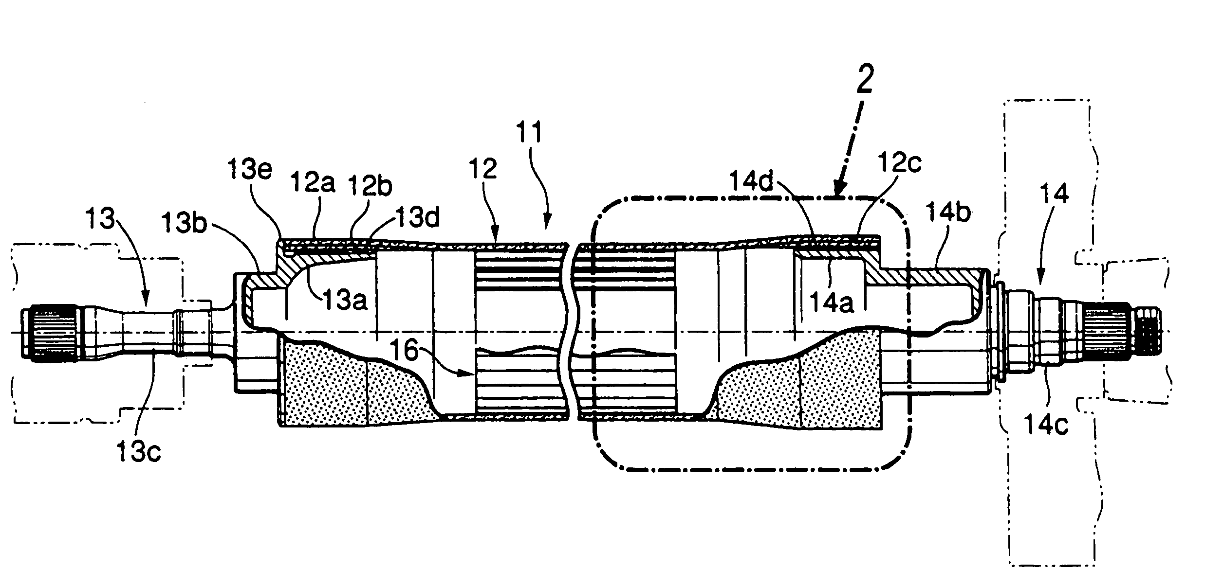
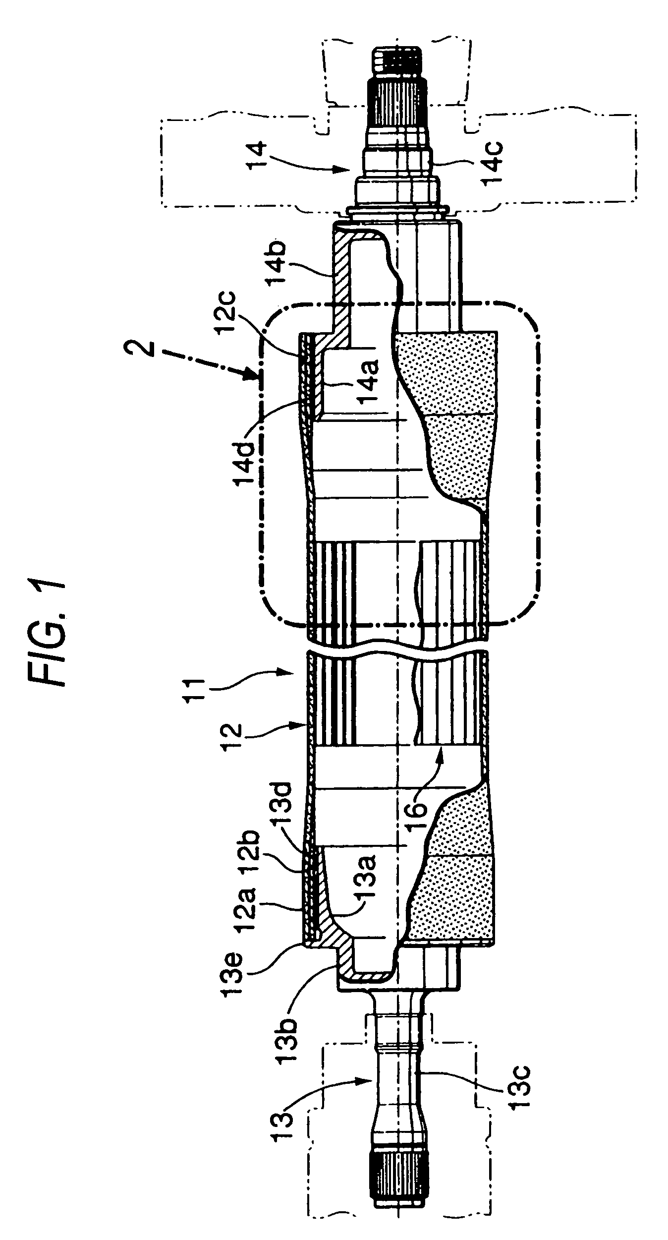
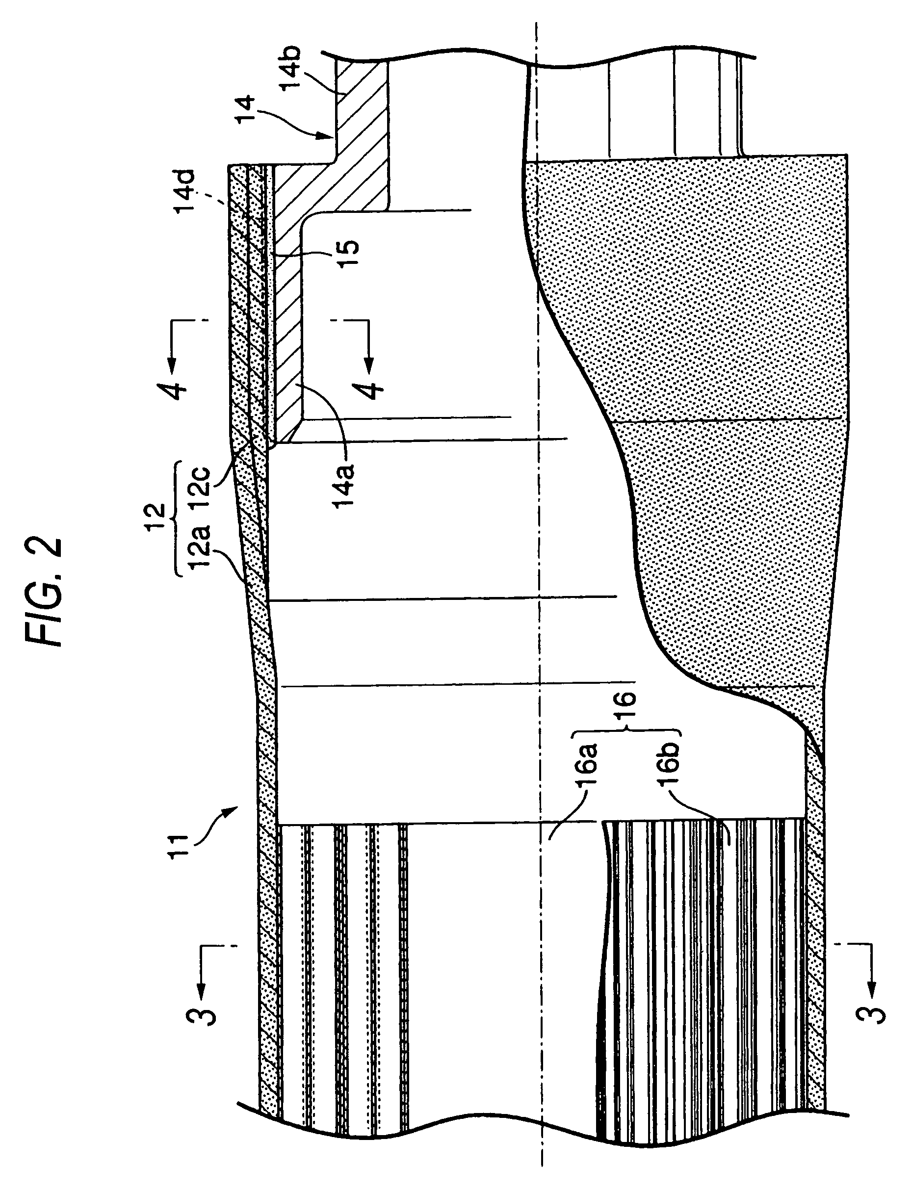
[0030]FIGS. 1 to 6 show an embodiment of the invention, in which FIG. 1 is a longitudinal sectional view of a propeller shaft, FIG. 2 is an enlarged view of a portion indicated by an arrow 2 in FIG. 1, FIG. 3 is a cross-sectional view taken along the line 3-3 in FIG. 2, FIG. 4 is a cross-sectional view taken along the line 4-4 in FIG. 2, FIG. 5 is a diagram which shows a state in which a single faced corrugated fiberboard is wound, and FIG. 6 is a diagram which explains a difference in elastic restoring force depending upon a direction in which the single faced corrugated fiberboard is wound.

[0031]As shown in FIGS. 1 to 4, a propeller shaft 11, which is disposed in a longitudinal direction of a body of an automobile in order to transmit the driving force of an engine installed in a front part of the body from a transmiss...


PUM


Abstract

A paper tube of a propeller tube 12 is made by winding a single faced corrugated fiberboard 16 in which a wavy corrugating medium 16b is fixed to one side of a flat linerboard 16a so that the corrugating medium 16b is oriented outwards, and the corrugating medium 16b contacts with an inner surface of the propeller tube 12, so as to enhance a vibration controlling function. When winding the single faced corrugated fiberboard 16, since the single faced corrugated fiberboard 16 cannot be wound in a direction oblique to a direction of ridges of the corrugating medium 16b, there are no fears that the shape of the single faced corrugated fiberboard 16 is collapsed to taper axially, thereby it becomes possible to prevent a reduction in vibration controlling function that would otherwise be caused due to a change in the shape of the paper tube.

Description

[0001]The present invention claims foreign priority to Japanese patent application No. P.2005-032523, filed on Feb. 9, 2005, the contents of which is incorporated herein by reference.BACKGROUND OF THE INVENTION[0002]1. Field of the Invention[0003]The present invention relates to a propeller shaft having a vibration controlling member made up of a paper tube within a propeller tube.[0004]2. Description of the Background Art[0005]In the event that gear meshing noise is transmitted to a propeller shaft which transmits the driving force of an engine of an automobile from a transmission or transfer to driving road wheels, a thin cylindrical propeller tube which makes up a main body portion of the propeller shaft resonates to thereby produce resonant noise when the frequency of the meshing noise coincides with the resonance frequency of the propeller tube.[0006]In order to suppress the resonant noise, in a propeller shaft described, for example, in Japanese Patent Unexamined Publication N...

Claims


Application Information

Patent Timeline
Patent Type & Authority Patents(United States)
IPC IPC(8): B63H21/21F16C3/00
CPCF16F15/10F16C3/026Y10T464/50F16C3/023F16C2326/06
Inventor WADA, SHINJIIIIZUMI, TOHRUINOUE, MASAKISUGIURA, YASUSHINISHIKOJI, TAKUYA
Owner HONDA MOTOR CO LTD
Why Eureka
Try Eureka