Method for adaptively compensating position error of resolver

a technology of resolver and position error, applied in the direction of speed/acceleration/shock measurement, instruments, surveying and navigation, etc., to achieve the effect of preventing the degradation of motor control performance caused by a position error, facilitating the implementation of the position error compensation of the resolver, and achieving maximum control performan

Active Publication Date: 2012-06-07
HYUNDAI MOTOR CO LTD +1
View PDF2 Cites 21 Cited by
  • Summary
  • Abstract
  • Description
  • Claims
  • Application Information

AI Technical Summary

Benefits of technology

[0020]Advantageously, it is possible to easily implement the position error compensation of the resolver, thereby automatically adapting a deviation between products. Accordingly, the degradation of motor control performance caused by a position error may be prevented, and the maximum control performance may be exhibited. For example, the pulsation of current and torque may be minimized, a speed measurement ripple may be reduced to enhance a control function using speed information, and a current ripple may be minimized to increase the available effective voltage, thereby securing a maximum output region.
[0021]Further, since the exemplary embodiment of the present invention may be implemented in a software manner which is executed by a processor, controller or the like without depending on an external separate physical unit, it is possible to simply compensate the position error of the resolver at a lower cost. Furthermore, since an expensive high-precision position sensor does not need to be used to secure the performance of the resolver, it is possible to implement a high-performance resolver system at an even lower cost.

Problems solved by technology

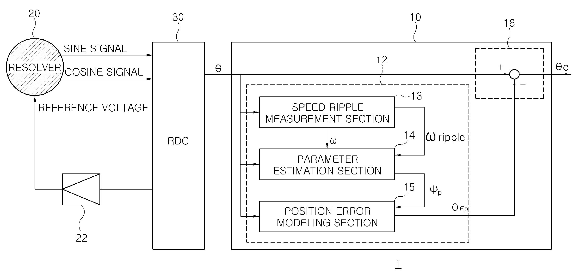
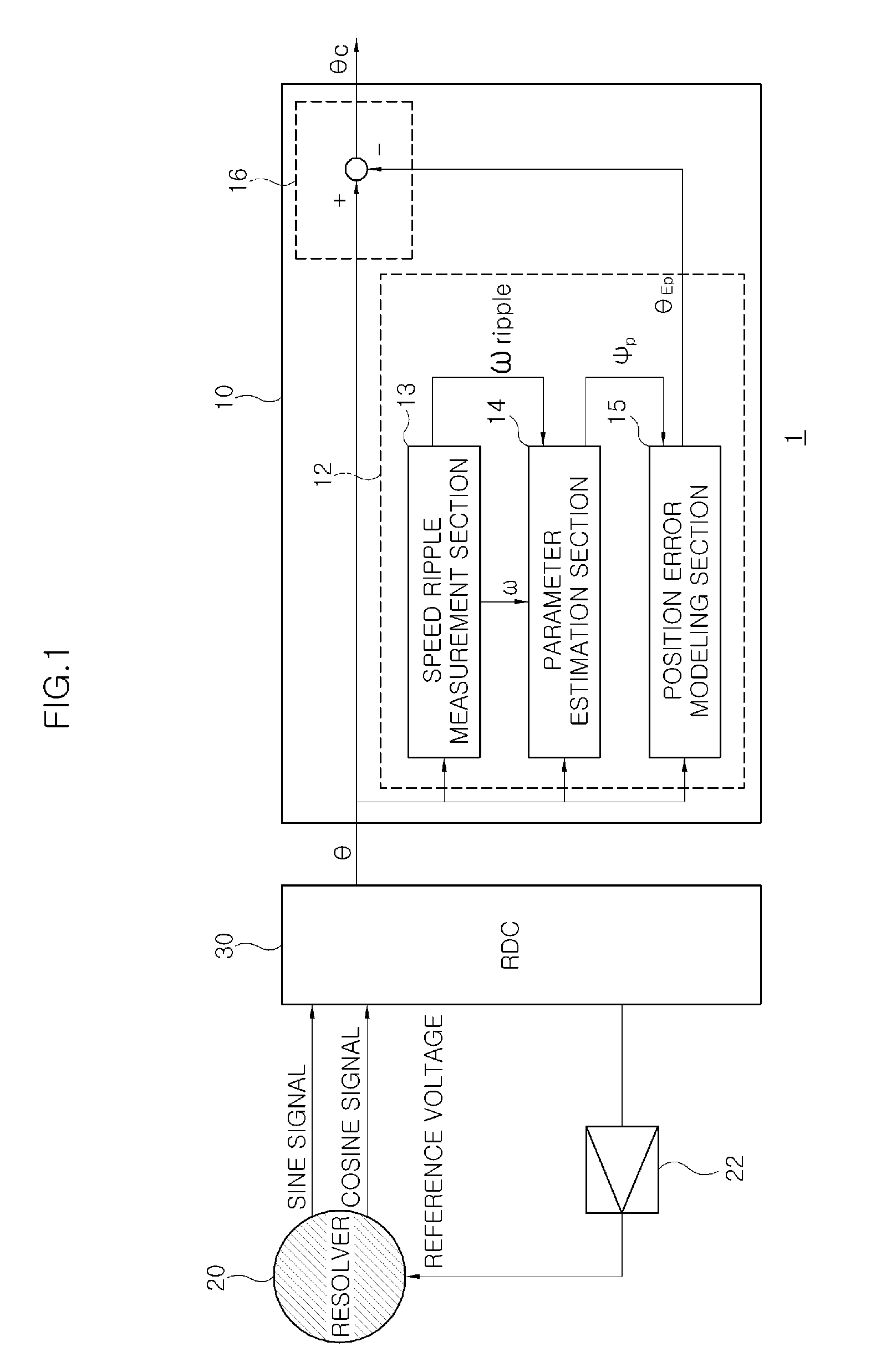
Furthermore, a position error modeling section creates a position error model equation by using the estimated unknown parameters and the position information, and estimates the position error from the position error model equation.

Method used


Image

  • Method for adaptively compensating position error of resolver
  • Method for adaptively compensating position error of resolver
  • Method for adaptively compensating position error of resolver

Examples


Embodiment Construction

[0031]Reference will now be made in detail to various embodiments of the present invention(s), examples of which are illustrated in the accompanying drawings and described below. While the invention(s) will be described in conjunction with exemplary embodiments, it will be understood that present description is not intended to limit the invention(s) to those exemplary embodiments. On the contrary, the invention(s) is / are intended to cover not only the exemplary embodiments, but also various alternatives, modifications, equivalents and other embodiments, which may be included within the spirit and scope of the invention as defined by the appended claims.

[0032]It is understood that the term “vehicle” or “vehicular” or other similar term as used herein is inclusive of motor vehicles having an electric motor in general such as passenger automobiles including sports utility vehicles (SUV), buses, trucks, various commercial vehicles, watercraft including a variety of boats and ships, airc...


PUM


Abstract

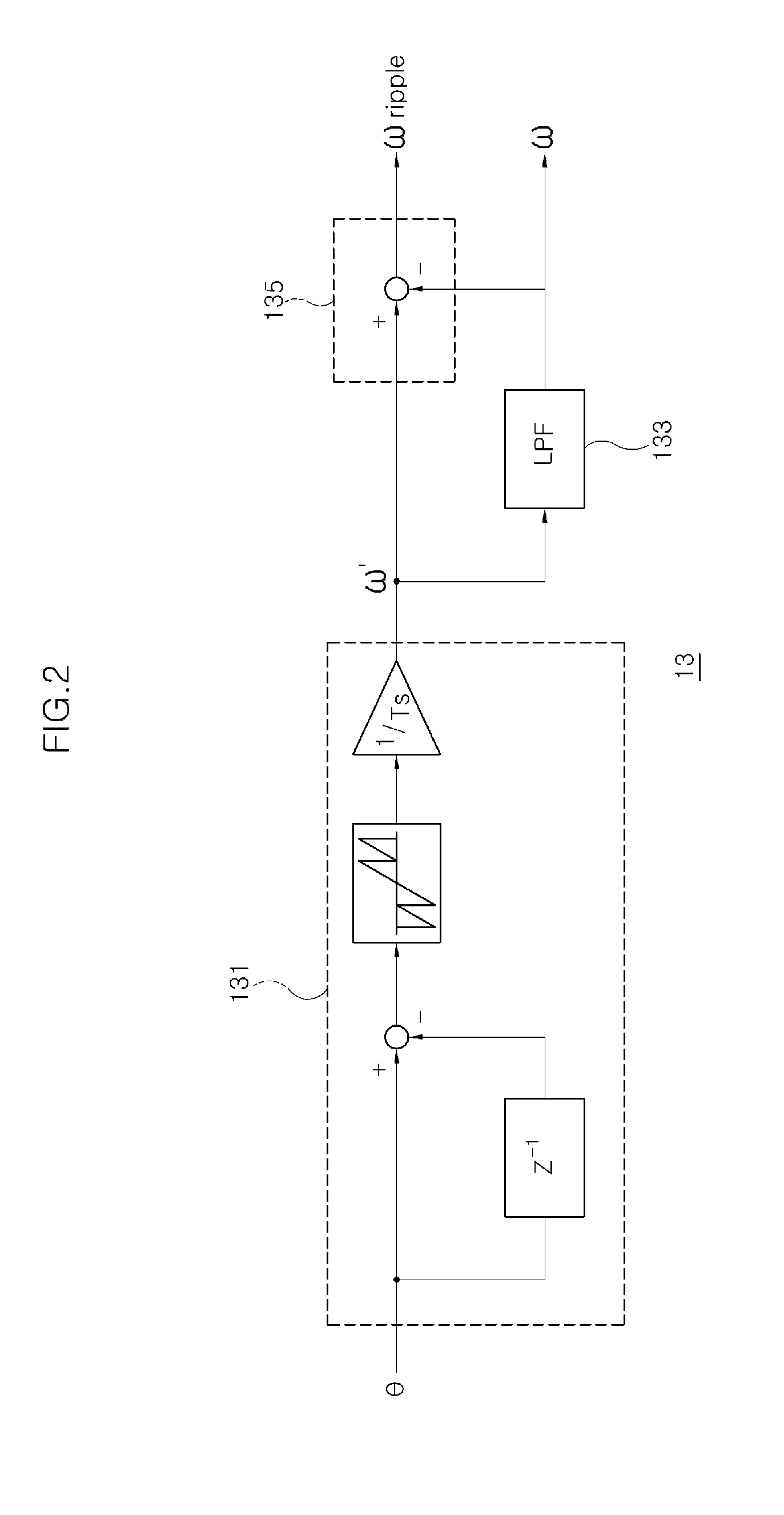
Disclosed are an apparatus and method for adaptively compensating a position error of a resolver. The apparatus adaptively estimating a position error contained in position information of a rotor of a motor, which is digitalized by a resolver-digital converter, and subtracting the estimated position error from the measured position information of the rotor, thereby calculating compensated position information. A regression equation and a recursive least square method applied to the regression equation are used for the adaptive estimation of the position information.

Description

CROSS-REFERENCE TO RELATED APPLICATIONS[0001]The present application claims priority to Korean Patent Application Number 10-2010-0121476 filed Dec. 1, 2010, the entire contents of which application is incorporated herein for all purposes by this reference.BACKGROUND OF THE INVENTION[0002]1. Field of the Invention[0003]The present invention relates to a method for compensating a position error contained in position information measured from a resolver which is a position sensor used for motor control.[0004]2. Description of Related Art[0005]When a permanent magnet synchronous motor is driven by vector control, accurate position information of a rotor thereof is required. Typically, a resolver (e.g., a pressure sensor) may be used to recognize the absolute position of the rotor. However, due to a difference in the transformation ratios of the resolver, unbalanced excitation signals, existence of inductance harmonic components, and distortion on a signal processing circuit, a magnitude...

Claims


Application Information

Patent Timeline
Patent Type & Authority Applications(United States)
IPC IPC(8): G06F19/00
CPCG01B21/00G01D5/24476G01B21/22
Inventor IHM, HYUNGBINCHUNG, TAEYOUNGYANG, BYUNGHOON
Owner HYUNDAI MOTOR CO LTD
Why Eureka
Try Eureka